Basic Civil & Mechanical Engineering: UNIT II: d. Levelling
Levelling
Objective, Uses, Terminology | Surveying
Levelling is a method of determining the relative heights or elevation of points above or below the surface of the Earth.
UNIT – II
Chapter - 3 (C)
LEVELLING
LEVELLING
Levelling
is a method of determining the relative heights or elevation of points above or
below the surface of the Earth. The elevation of a point is the vertical
distance above or below a reference surface called Datum. Datum is the Mean Sea
Level (M.S.L.). Thus, levelling deals with the measurements in a vertical
plane.
1. OBJECTIVE and USES OF LEVELLING IN SURVEYING :
i)
Levelling is necessary to determine the difference in levels of points or
objects.
ii)
Purposes of Levelling are: Deciding the depth of excavation for foundations,
Determining the depths and heights of cuttings and embankments on highways
roads and railway constructions, Setting out gradients for pipelines, dams,
bridges, etc.
iii)
Levelling provides an accurate network of heights covering the entire area of
the project.
iv)
Contour Map of an area may be plotted by levelling.
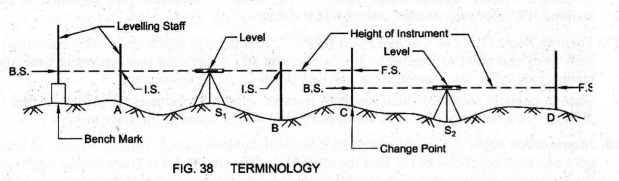
2. TERMINOLOGY (Fig. 38)
1.
Level Surface: A Level Surface is a surface which is,
at all points, normal to the direction of gravity indicated by a plumb line.
Due to the spherical shape of the Earth, a level surface is not a plane. The
surface of still water in a lake is a level surface.
2.
Level Line: It lies on one level surface. So it is
normal to the direction of gravity at all points.
3.
Horizontal Plane: Horizontal Plane is a plane
perpendicular to the direction of gravity.
4.
Horizontal Line: Horizontal Line is a straight line
lying in the horizontal plane.
5.
Vertical Line: Vertical Line is a line indicated by a
freely suspended plumb bob. Hence, it is also known as Plumb Line. It is the
line along the direction of gravity.
6.
Vertical Plane: Vertical Plane is a plane containing a
vertical line at a point.
7.
Axis of Telescope: It is a line joining the optical
center of the object glass and the eye piece.
8.
Axis of Level Tube or Bubble Tube: It is a straight line
tangential to the longitudinal curve of the level tube at its center. It is
horizontal when the bubble is central.
9.
Line of Collimation or Line of Sight: It is a
straight line joining the intersection of cross hairs of the diaphragm and the
optical center of the object glass and its continuation.
10.
Staff Station: It is a point where the staff is held
for taking observation from a leveling instrument. It is the point whose
elevation is to be determined for a given elevation. Station denotes staff
point, not the point where the level is setup.
11.
Datum Surface: Datum Surface is an imaginary or any
arbitrarily assumed level surface, from which vertical distances of the points
above or below the surface are measured. The datum surface adopted by the Great
Trigonometrical Survey (G.T.S.) department of India is the Mean Sea Level at
Bombay Port, which is taken as zero.
12.
Reduced Level (R.L.) or Elevation of a Point: It is the
height or depth of a point above or below the assumed datum surface.
13.
Bench Mark (B.M.): Bench Mark is a fixed reference
point of known elevation above or below the datum surface. Any permanent
reference point whose elevation with respect to some assumed datum is known can
be used as bench mark. The Reduced Level of Bench Mark is used to determine the
reduced levels of other points.
Examples:
Kilometer Stone, Road Kerb, Top of Culvert, Plinth Level of Building, etc.
14.
Back Sight (B.S.): Back Sight is taken on a rod held
at a point of known elevation to obtain the height of the instrument. It is the
first staff reading taken after setting up the instrument in any position. This
will always be a reading on a point of known height. Back sight is also known
as Plus Sight.
15.
Height of Instrument (H.I.) or Height of Collimation (H.C.):
It is the elevation or reduced level of the line of sight of the levelling
instrument when it is levelled. Note that H.I. is not the height of telescope
from the ground. Back Sight (B.S.) is used to determine the Height of
Instrument (H.I.). i.e., Height of Instrument (H.I.) = Known elevation of the
point + B.S.
16.
Fore Sight (F.S.): It is a sight taken on a rod held
at a point of known elevation to obtain the Reduced Level of the station. It is
the last staff reading taken on a point before shifting instrument. This will
always be a point whose height has to be determined. Fore Sight is also known
as Minus Sight. F.S. is used to determine the elevation of staf stations. i.e.,
elevation of staff station = H.I. - F.S.
17.
Turning Point (T.P.) or Change Point (C.P.):
It is the one which makes the instrument to shift from one point to another. It
is a point on which both the fore sight and back sight readings are taken from
the previous and new positions of the instrument. Change point is selected when
the level is to be setup at a number of places to find the elevation of a far
away point. A bench mark may also be taken as a change point.
18.
Intermediate Sight (I.S.): It is a point
intermediate between two Turning Points, on which only one Fore Sight is taken
to find the elevation of the station. It is also a Minus Sight. I.S. is also
used to find the elevation of staff stations. i.e., elevation of staff station
= H.I. - I.S.
Basic Civil & Mechanical Engineering: UNIT II: d. Levelling : Tag: : Objective, Uses, Terminology | Surveying - Levelling
Related Topics
Related Subjects

Basic Civil and Mechanical Engineering
BE3255 2nd Semester 2021 Regulation | 2nd Semester EEE Dept 2021 Regulation