Electric Circuit Analysis: Unit II: Network Reduction and Theorems for dc and ac Circuits
Maximum Power Transfer Theorem
Statement, Circuit Diagram, Equation, Steps, Calculation, Solved Example Problems
Electric Circuit Analysis: Unit II: Network Reduction and Theorems for dc and ac Circuits : Worked examples
4. Maximum Power Transfer Theorem EST
The
statement of this theorem depends upon the conditions of the circuit. We shall
consider three cases one by one as below :
Case
1: Purely resistor circuit and the load resistance is
variable.
Statement:
"Maximum
power will be delivered from a voltage source to a load, when the load
resistance is equal to the internal resistance of the source."
For
example, consider a voltage source of generated voltage Vg and
internal resistance Rg, connected to a load resistance RL
as shown in the figure.
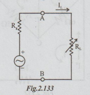
When
the power transfer to the load is maximum RL = Rg. At
this condition the total resistance = Rg + RL = 2RL.
Therefore,
the load current = IL = Vg / 2RL
Power
delivered to RL = IL2 RL
=
(Vg / 2RL )2 RL = Vg2 /
4RL
The
maximum power transferred to RL
i.e.,
Pmax = Vg2 / 4RL
Under
this condition the efficiency is only 50%, since one-half of total power
generated is lost in dissipation within the source.
Note:
(i)
The reader is to note that the maximum current and the maximum power transfer
will not take place for the same value of RL.
(ii)
Current is maximum when RL is 0 and is given by Vg / Rg
(iii)
Power transfer is maximum when RL = Rg.
(iv)
Current at maximum power is 50% of maximum current.
Case
2: Reactances present, and load resistance and
reactance can be independently varied.
Statement:
"Maximum power will be delivered from a voltage source to a load when the
load impedance is the complex conjugate of the source impedance. In this case,
Rg and RL of the above figure are replaced by Zg and ZL
respectively. Zg = the internal impedance of the source = RgL +
jXg and ZL = load impedance = RL + j XL
. XL is the load reactance but not inductive reactance. According to
maximum power transfer theorem, ZL = complex conjugate of Zg
= Rg – jXg. Hence when the power transfer is maximum the
total impedance = 2 RL.
Case
3: Reactances present, but only the magnitude of the
load impédance can be varied.
Statement:
"Maximum power is delivered from a voltage source of the load when the
magnitude of the load impedance is equal to the magnitude of the source
impedance." Let O be the angle of the load impedance.
So
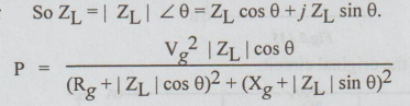
For
maximum power transfer, we must have dP / d | ZL | = 0.
Using
this condition and simplifying the above equation, we get
Rg2
+ Xg2 = | ZL |2 or, | Zg | = | ZL |
Note:
1.
It may be mentioned that this condition holds good for a transformer, where the
turns ratio is varied for maximum power transfer. Ex01-
2.
If the source impedance is purely resistive Rg and load impedance
consists of variable RL and fixed reactance X, then, for maximum
power transfer RL2 = Rg2 + X2.
3.
If the load impedance is pure resistive equal to RL, but the source
impedance consists of both resistance and reactance, the power delivered to the
load can be maximised by varying RL. The power transfer is maximum
when RL2 = Rg2 + Xg2.
(or) RL = | Zg |.
4.
When conditions for maximum power transfer to the load are satisfied, the load
is said to be matched to the source.
Important
clue for solving any problem on maximum power transfer theorem.
The
reader must first get the Thevenin's equivalent for a given circuit between the
output terminals A and B across which the load impedance or load resistance is
connected.
WORKED EXAMPLES
MAXIMUM POWER TRANSFER
Example 1 The circuit shown in the figure, R absorbs maximum power. Compute the value of R and maximum power.
Solution: Thevenin's equivalent circuit is drawn as below :
To find VTh: Disconnect R from the original circuit.
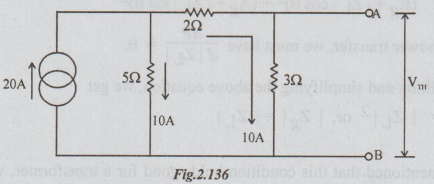
VTh = VAB = -10 × 3 = - 30 volts
= 30 volts [with B negative and A positive]
To find RTh: From the above circuit, open circuit the current source. Thus,
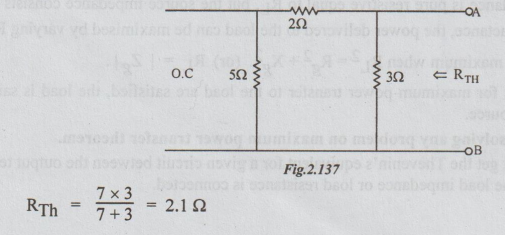
According to the statement of maximum power transfer theorem, the value of R for maximum power transferred to it = RTh = 2.1 Ω and the maximum power transferred
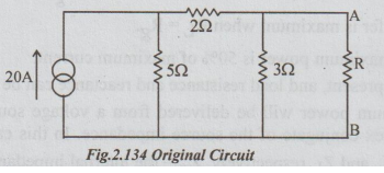
Example 2 A loud speaker is connected across the terminals A and B of the network shown in figure below. What should be the value of impedance of the speaker to obtain maximum power transferred to it and what is the maximum power?

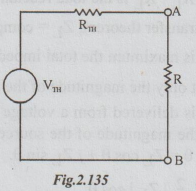
Solution: The Thevenin's equivalent circuit is as shown above.
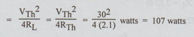
To find VTh: In the original circuit the current
To find ZTh: From the original circuit, killing the voltage source, the following circuit is obtained.

For maximum power transfer, let the load impedance be ZL = RL + j XL, both being variables.

Example 3 For the circuit of the figure, find the value RL for maximum power delivered to it. Calculate also the maximum load power.

Solution: Step 1: To find VTh: Disconnect RL between A and B terminals.
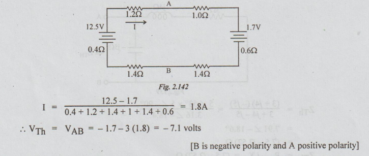
[B is negative polarity and A positive polarity]
Step 2: To find RTh: Kill the sources from the circuit in the step 1 to get the following circuit.

Step 3: Thevenin's equivalent circuit is drawn as below:

From this, we can say that the values of RL for maximum power transferred to it

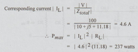
Example 4 In the circuit of fig. below, find the value of RL which results in maximum power and calculate the value of maximum power.

Solution: From the given circuit, the value of RL for maximum power transferred to it = | Zg | = | 10 + j5 | = 11.18 Ω.
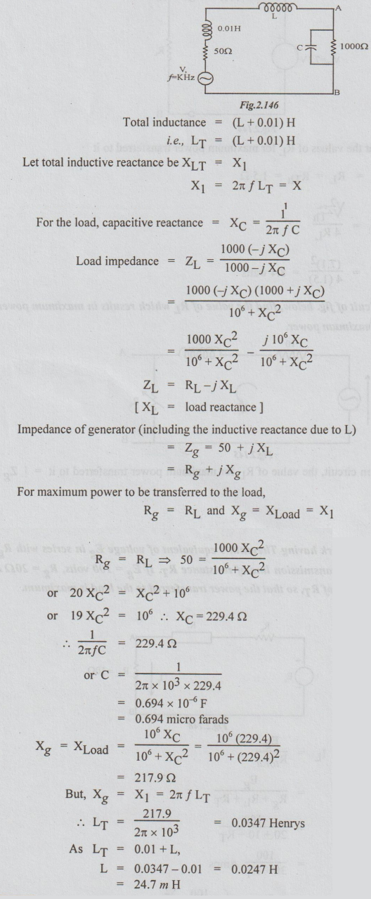
Example 5 A 1 KHz generator has an internal impedance containing a resistance of 502 in series with and inductance of 0.01 H. It is supplying a load of 1000 Ω resistance. A capacitor is connected in parallel with the load and a circuit of inductance L and negligible resistance is put in series with the generator. Find the values of C and L which will give maximum power in the load.
Example 6 A load impedance of (20 - j XC) Ω is supplied from a source of e.m.f. 10V r.m.s. and internal impedance (10 + j20) Ω Find the value of Xc to give maximum power dissipation in the load and calculate the value of this power.

Solution: If the load resistance as well as load reactance are variables, the load must be conjugate of the source impedance for maximum power transfer. If the reactance alone is variable, the load reactance = source reactance, with opposite nature. Hence XC = 20Ω.
Total impedance = Ztotal

Example 7 A network having Thevenin's equivalent of voltage Eg in series with Rg supplies a load of RL through a transmission line of resistance RT. If Eg = 100 volts, Rg = 202 and RL = 10Ω, determine the value of RT, so that the power transferred to the load is maximum.
Solution:

WORKED EXAMPLES
MAXIMUM POWER TRANSFER
Example 1 The circuit shown in the figure, R absorbs maximum power. Compute the value of R and maximum power.
Solution: Thevenin's equivalent circuit is drawn as below :
To find VTh: Disconnect R from the original circuit.
VTh = VAB = -10 × 3 = - 30 volts
= 30 volts [with B negative and A positive]
To find RTh: From the above circuit, open circuit the current source. Thus,
According to the statement of maximum power transfer theorem, the value of R for maximum power transferred to it = RTh = 2.1 Ω and the maximum power transferred
Example 2 A loud speaker is connected across the terminals A and B of the network shown in figure below. What should be the value of impedance of the speaker to obtain maximum power transferred to it and what is the maximum power?
Solution: The Thevenin's equivalent circuit is as shown above.
To find VTh: In the original circuit the current
To find ZTh: From the original circuit, killing the voltage source, the following circuit is obtained.
For maximum power transfer, let the load impedance be ZL = RL + j XL, both being variables.
Example 3 For the circuit of the figure, find the value RL for maximum power delivered to it. Calculate also the maximum load power.
Solution: Step 1: To find VTh: Disconnect RL between A and B terminals.
[B is negative polarity and A positive polarity]
Step 2: To find RTh: Kill the sources from the circuit in the step 1 to get the following circuit.
Step 3: Thevenin's equivalent circuit is drawn as below:
From this, we can say that the values of RL for maximum power transferred to it
Example 4 In the circuit of fig. below, find the value of RL which results in maximum power and calculate the value of maximum power.
Solution: From the given circuit, the value of RL for maximum power transferred to it = | Zg | = | 10 + j5 | = 11.18 Ω.
Example 5 A 1 KHz generator has an internal impedance containing a resistance of 502 in series with and inductance of 0.01 H. It is supplying a load of 1000 Ω resistance. A capacitor is connected in parallel with the load and a circuit of inductance L and negligible resistance is put in series with the generator. Find the values of C and L which will give maximum power in the load.
Example 6 A load impedance of (20 - j XC) Ω is supplied from a source of e.m.f. 10V r.m.s. and internal impedance (10 + j20) Ω Find the value of Xc to give maximum power dissipation in the load and calculate the value of this power.
Solution: If the load resistance as well as load reactance are variables, the load must be conjugate of the source impedance for maximum power transfer. If the reactance alone is variable, the load reactance = source reactance, with opposite nature. Hence XC = 20Ω.
Total impedance = Ztotal
Example 7 A network having Thevenin's equivalent of voltage Eg in series with Rg supplies a load of RL through a transmission line of resistance RT. If Eg = 100 volts, Rg = 202 and RL = 10Ω, determine the value of RT, so that the power transferred to the load is maximum.
Solution:
Electric Circuit Analysis: Unit II: Network Reduction and Theorems for dc and ac Circuits : Tag: : Statement, Circuit Diagram, Equation, Steps, Calculation, Solved Example Problems - Maximum Power Transfer Theorem
Related Topics
Related Subjects

Electric Circuit Analysis
EE3251 2nd Semester 2021 Regulation | 2nd Semester EEE Dept 2021 Regulation