Electric Circuit Analysis: Unit II: Network Reduction and Theorems for dc and ac Circuits
Milliman's Theorem
Statement, Circuit Diagram, Equation, Steps, Calculation, Solved Example Problems
Electric Circuit Analysis: Unit II: Network Reduction and Theorems for dc and ac Circuits : Worked examples
6. Milliman's Theorem
This theorem enables a number of voltage (or current) sources to be combined into a single voltage (or current) source.
Statement: (For voltage sources): In any network, if the voltage V1, V2,.......Vn with internal independences Z1, Z2,......... Zn respectively, are in parallel, then, these sources may be replaced by a single voltage source V in series with Z.
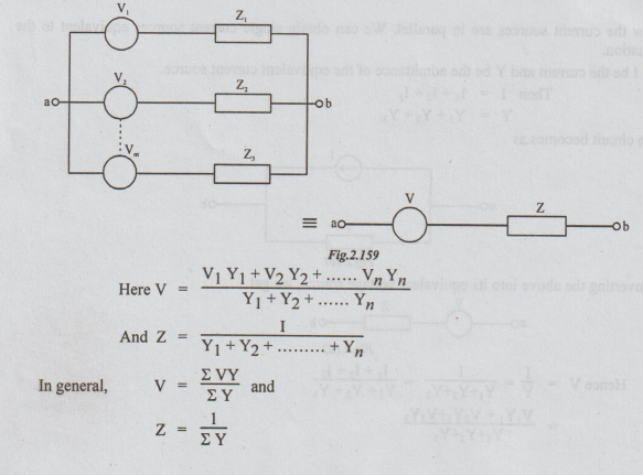
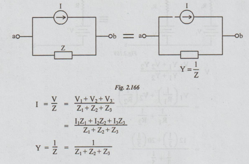
Proof: In the given circuit, converting each voltage source into its equivalent source, we get
Now the current sources are in parallel. We can obtain single current sources equivalent to the combination.
Let I be the current and Y be the admittance of the equivalent current source.
Then I = I1 + I2 + I3
Y = Y1 + Y2 + Y3
The circuit becomes as
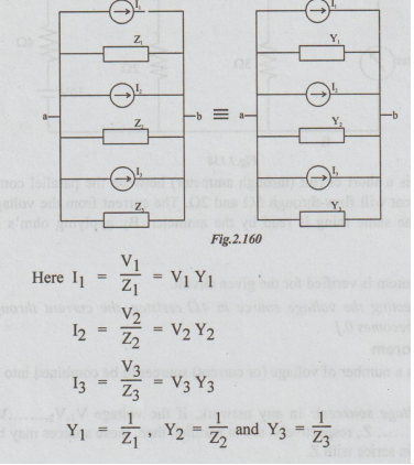
For current sources:
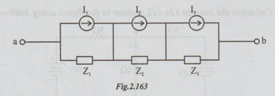
Consider 3 current sources of I, I, and I, having internal impedances Z1, Z2 and Z3 connected in series. Our aim is to replace the same by a single source.
Step 1: Convert each current source into its equivalent voltage source.
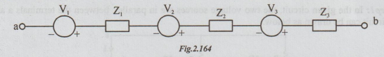
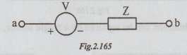
Step 2: Since all the 3 voltage sources are series, replace them by single voltage source of voltage V and internal impedance Z.
V = V1+ V2 + V3
Z = Z1 + Z2 + Z3
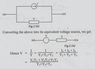
Step 3: The equivalent current source is
WORKED EXAMPLES
Example
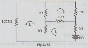
1 For the circuit shown in the figure below, find 13 and verify reciprocity
theorem.
Solution:
Step 1: By inspection putting in the matrix form, we get

Step
2: Transferring the battery, to the branch with 1.375 Ω
resistor, the following circuit is obtained. The current through 1 Ω is taken
as I3. According to reciprocity theorem this I3 = 2A.
Let
us calculate the value of I3 in figure below:

Thus
reciprocity theorem is verified.
Note:
In the above problem, the current 13 can be found by branch current method. In
that case both KCL and KVL are to be applied. It is solved here by loop current
method, where only KCL is to be applied. This method is preferred to loop
current method.
Example
2 Verify reciprocity theorem in the circuit shown in the figure and also
calculate the transfer resistance.

Solution:
Step 1:
Voltage
across 8 ohms = V = Ig × R
But
Ig = 10 × 2 / 2 + 8 = 2A
R
= 8Ω
V
= 2 × 8 = 16V
Step
2: Interchanging the current source and response, the
circuit becomes as below: Here the response is V.

V
= I2 × R, R = 2Ω, since the current 2
In
both cases, the ratio of voltage to current is the same. Hence the reciprocity
theorem is verified.
The
transfer resistance = V/ I = 16/10 = 1.6Ω
Example
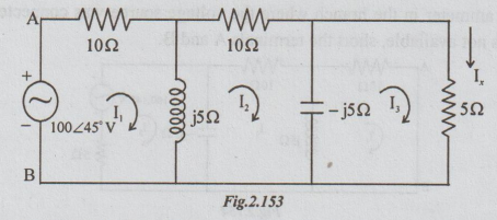
3 In the network shown in the figure, the voltage source 100 ∠
45°V causes current Ix in the 5Ω branch. Find Ix
and then verify the reciprocity theorem for this circuit.
Solution:
Step 1: It is required to find the value of Ix.
Let us apply loop current method. If the loop currents are taken to be I1,
I2 and I3 as shown, then Ix = I3.
For
the above circuit, by inspection, we can write that

Step
2: Now connect the voltage source in the branch in
which the current is I, i.e., in 52 branch and connect an a.c. ammeter in the
branch where the voltage source was connected earlier as shown below. If
ammeter is not available, short the terminals A and B.
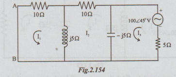
If
the current through AB is same as the value of Iy in the step 1, we can say
that the reciprocity theorem is verified. To calculate the current let us again
prefer loop current method to other methods.
By
inspection.

Hence
the reciprocity theorem is verified.
Example
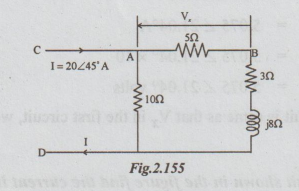
4 In the circuit shown determine Vx Then apply the reciprocity theorem and
compare the 2 voltages.
Solution
: Step 1 : Vx = I5 × 5
Is
is the current through the series combination of 5Ω, 3Ω and j8Ω.
I5
= 20 ∠ 45° × 10 / 10 + 5 + 3 +
j8
=
200 ∠ 45° / 19.7 ∠ 23.96°
=
10.15 ∠ 21.04°A
Vx
= 10.15 ∠ 21.04° (5 ∠ 0°)
=
50.75 ∠ 21.04° V
Step
2: Connecting the current source across 5 and
voltmeter across C and D, the circuit becomes as:
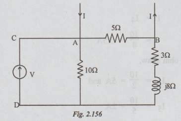
The
voltage across CD = V = Voltage across 10Ω
To
find the voltage across 10Ω, current through it must be known. As is shown in
the circuit, the source current I is divided into two parallel paths. A part of
I flows through 5Ωand remaining flows through the series combination of 10Ω, j8Ω
and 3Ω.
By
current division formula current through 10Ω = I10
=
20 ∠ 45° × 5 / 10 + j 8 + 3 +
5
=
100 ∠ 45° / 18 + j8
=
100 ∠ 45° / 19.7 ∠ 23.96
=
5.075 ∠ 21.04°A
V
= 5.075 ∠ 21.04° × 10
=
5.075 ∠ 21.04° volts
As
this V in the second circuit is same as that Vx in the first circuit, we can
say that the reciprocity x theorem is verified.
Example
5 In the circuit shown in the figure find the current in the 42 resistor. Apply
the reciprocity theorem and compare the 2 currents. What change results in the
current through 5Ω and 2Ω branches?
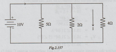
Step
1: In the given circuit, the resistors 402, 22 and 502
are all in parallel across the 10V source. As shown
I
= I4
=
10 / 4 = 2.5 A
Similarly
by applying ohm's law,
I2
= 10 / 2 = 5 A and
I5
= 10 / 5 = 2A
Step
2: Connecting the voltage source in the 452 branch and
D.C. ammeter (of negligible resistance) in place of the voltage source of the
given circuit we get the following:
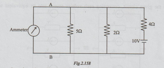
In
this figure, there is a short circuit (through ammeter) between the parallel
combination of 5Ω and 2Ω. Hence, no current will flow-through 5Ω and 2Ω. The
current from the voltage source flows through only 4Ω and the same thing is
read by the ammeter. By applying ohm's law, reading of ammeter 10/4 = 2.5A.
Thus,
reciprocity theorem is verified for the given circuit.
[Note: After connecting the voltage source in 4Ω resistor, the current through branches of resistances 2Ω and 5 Ω becomes 0.]
Electric Circuit Analysis: Unit II: Network Reduction and Theorems for dc and ac Circuits : Tag: : Statement, Circuit Diagram, Equation, Steps, Calculation, Solved Example Problems - Milliman's Theorem
Electric Circuit Analysis: Unit II: Network Reduction and Theorems for dc and ac Circuits
Under Subject

Electric Circuit Analysis
EE3251 2nd Semester 2021 Regulation | 2nd Semester EEE Dept 2021 Regulation
Related Subjects

Professional English II
HS3251 2nd Semester 2021 Regulation | 2nd Semester Common to all Dept 2021 Regulation

Statistics and Numerical Methods
MA3251 2nd Semester 2021 Regulation M2 Engineering Mathematics 2 | 2nd Semester Common to all Dept 2021 Regulation

Engineering Graphics
GE3251 eg 2nd semester | 2021 Regulation | 2nd Semester Common to all Dept 2021 Regulation

Physics for Electrical Engineering
PH3202 2nd Semester 2021 Regulation | 2nd Semester EEE Dept 2021 Regulation

Basic Civil and Mechanical Engineering
BE3255 2nd Semester 2021 Regulation | 2nd Semester EEE Dept 2021 Regulation
Electric Circuit Analysis
EE3251 2nd Semester 2021 Regulation | 2nd Semester EEE Dept 2021 Regulation

Physics for Electronics Engineering
PH3254 - Physics II - 2nd Semester - ECE Department - 2021 Regulation | 2nd Semester ECE Dept 2021 Regulation

Electrical and Instrumentation Engineering
BE3254 - 2nd Semester - ECE Dept - 2021 Regulation | 2nd Semester ECE Dept 2021 Regulation

Circuit Analysis
EC3251 - 2nd Semester - ECE Dept - 2021 Regulation | 2nd Semester ECE Dept 2021 Regulation

Materials Science
PH3251 2nd semester Mechanical Dept | 2021 Regulation | 2nd Semester Mechanical Dept 2021 Regulation

Basic Electrical and Electronics Engineering
BE3251 2nd semester Mechanical Dept | 2021 Regulation | 2nd Semester Mechanical Dept 2021 Regulation

Physics for Civil Engineering
PH3201 2021 Regulation | 2nd Semester Civil Dept 2021 Regulation

Basic Electrical, Electronics and Instrumentation Engineering
BE3252 2021 Regulation | 2nd Semester Civil Dept 2021 Regulation

Physics for Information Science
PH3256 2nd Semester CSE Dept | 2021 Regulation | 2nd Semester CSE Dept 2021 Regulation

Basic Electrical and Electronics Engineering
BE3251 2nd Semester CSE Dept 2021 | Regulation | 2nd Semester CSE Dept 2021 Regulation

Programming in C
CS3251 2nd Semester CSE Dept 2021 | Regulation | 2nd Semester CSE Dept 2021 Regulation