Electric Circuit Analysis: Unit II: Network Reduction and Theorems for dc and ac Circuits
Solved Example Problems: Thevenin's, Norton's Theorem
Electric Circuit Analysis: Unit II: Network Reduction and Theorems for dc and ac Circuits : Worked examples
BOOT WORKED EXAMPLES
THEVENIN'S THEOREM
Example 1 Determine the current I in the network by using Thevenin's theore
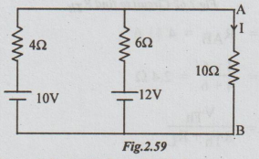
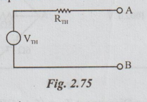
Solution: Step 1. The Thevenin's equivalent circuit is

Step 2: To find VTh: From the given circuit disconnect RL = 10 Ω

Step 3: To calculate RTh: From the above circuit, kill the sources. The resultant circuit is

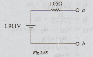
Example 2 Find the Thevenin's equivalent for the network of the figure between a and b.
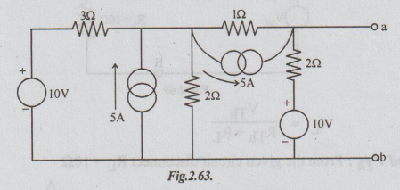
Solution: The network given is a combination of voltage and current sources. By converting voltage source into current source and vice-versa, wherever necessary and simplifying we can obtain the required network.
Step 1: Converting or transforming the voltage source of 10V in series with resistance 32 into equivalent current source, the following circuit is obtained.

Step 2: Replacing the 2 current sources in parallel by its equivalent current source, we get the following circuit.
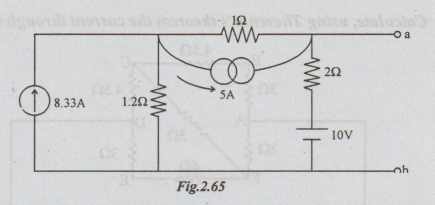
Step 3: Transforming the 2 current sources in series by their equivalent voltage sources we get the following network.

Step 4: Transforming the voltage sources which are parallel in the above circuit, into their equivalent current sources we get the following network.

Step 5: Converting the current source into equivalent voltage source, we get the Thevenin's equivalent circuit as shown below:
Note: From step 3, we can proceed to find VTh and RTh without going through step 4.
Example 3 Calculate, using Thevenin's theorem the current through the branch FC.
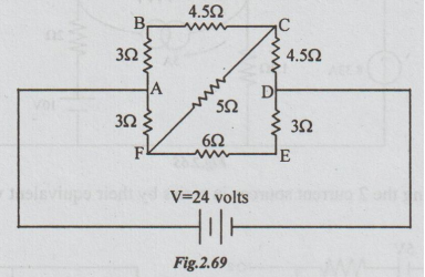
Solution: Step 1: The Thevenin's equivalent circuit is,

Step 2: To calculate VTh:
Disconnect RL = 5 Ω, between F and C terminals.
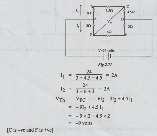
Step 3: To calculate RTh: Re-draw the above circuit, after killing the voltage source.

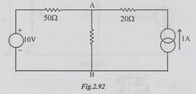
Example 4 It is required to find current through the 0.12 resistor in the figure, using Thevenin's method.
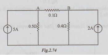
Solution: Step 1: The Thevenin's equivalent circuit :
Solution: Step 2: To calculate VTh: From the given network disconnect (remove) RL = 0.1 Ω
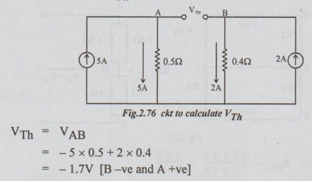
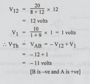
VTh = VAB
= -5 × 0.5 + 2 × 0.4
= -1.7V [B-ve and A +ve]
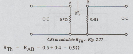
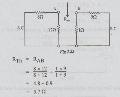
Step 2: To calculate RTh: Kill the current source in the above circuit by open circuit (O.C.)
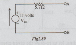
Step 3:

[Note: The above problem can also be solved by other methods such as source conversion method and superposition principle.]
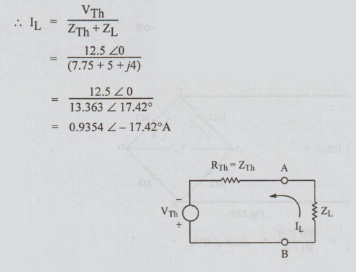
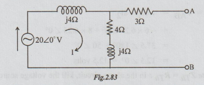
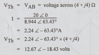
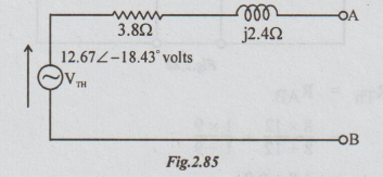
Example 5 Use Thevenin's theorem and find the current through (5+ j4) Ω impedance in the figure.
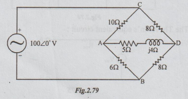
Solution: Step 1: To find VTh: Disconnect ZL = (5+j4) Ω

Step 2: To calculate ZTh = RTh: In the above circuit, kill the voltage source, by shorting C and D terminals.
Step 3: Thevenin equivalent ckt
Example 6 Find the Thevenin's equivalent circuit for the network given in the figure.
Solution: Step 1: To find VTh: In the original circuit, A and B terminals are shown open circuited.
[Note: As 3 Ω is in open circuit, no current flows through it and hence no voltage drop occurs across it.]
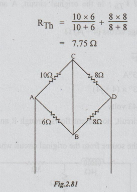
Step 2: To find ZTh: Kill the source from the original circuit where ZL is already removed.

Step 3: The Thevenin's equivalent circuit constant voltage generator circuit is
Example 7 Determine Thevenin's equivalent across the terminals A and B.

Solution: For clear understanding, let us re-draw the given circuit as shown below:

Step 1: To find VTh: For each loop, there are two resistors in series. By distribution of voltage formula,
Step 2: To calculate RTh: Killing the source in the circuit shown in the fig. above, we get the following passive network.
The Thevenin's equivalent circuit becomes as below:
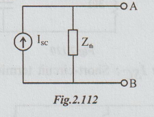
NORTON'S THEORM
WORKED EXAMPLES
Example
1 Determine the voltage across 2002 resistor in circuit by Norton's theorem.
Solution:
Step 1: To find the short circuit current ISC.
Replace the 200 2 by short circuit. The current through short circuited AB is ISC.
Refer the following figure.
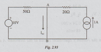
The
voltage source will drive a current of 10/50 = 0.2 A, which flows through short
circuited AB only. Similarly the current of 1A flows through 20 and then
through short-circuited AB only. 0.2 A will not flow through 20 Ω
and 1A will not flow through 50 Ω. It is because of
short-circuit. So, ISC = 0.2+1= 1.2A.
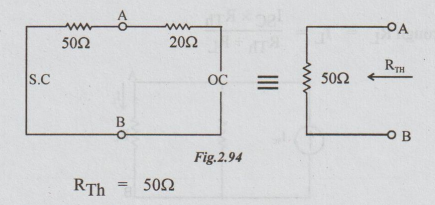
Step
2: To find RTh: From the given
circuit, disconnect RL = 200 Ω between A and B and also kill the
sources. The resultant circuit becomes as below:
Step
3: Drawing Norton's equivalent circuit and showing the
load resistance RL, we get the following circuit:

Example
2 Obtain the Norton's equivalent circuit at the terminals A and B for the
network shown.

Solution:
Step 1: To calculate ISC: Short circuit A and B
terminals to get the following circuit.
As
10 Ω
is shorted, no current flows through it. Hence ISC = I2.
Neglect presence of 10 Ω. By inspection,
Step
2: To find RTh: From the original
circuit kill the sources. Remember that 100 must be taken and it is effective.

Step
3: Norton's equivalent circuit is
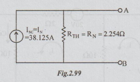
[Note: The student is advised to
find Thevenin's equivalent ckt for the above problem.]
[Ans: VTh = 85.94
volts and RTh = 2.254 Ω]
Example
3 Obtain the Norton's equivalent circuit at the terminals A and B for the
network shown.
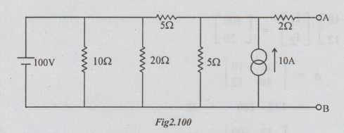
Solution:
10 Ω
and 20 Ω
are connected across the ideal voltage source. Hence these resistors can be
removed without altering the performance of the network. Also converting the
current source into voltage source we get the following circuit :

Norton's
equivalent can be found for the above circuit by converting the Thevenin's
equivalent source into current source. Or, we can directly find the Norton's
equivalent which is done as below:
Step
1: To find short-circuit current. Short circuit the
terminals A and B to obtain the following circuit:

By
loop current method, we can write that
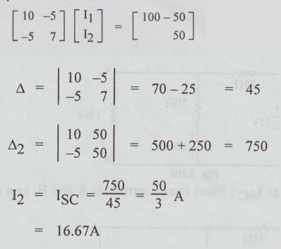
Step
2 : To find RTh : Killing the sources
and keeping A and B terminals open, we get

[Note
: The student is advised to solve the above problem without removing the
resistance of 10 Ω and 20 Ω. He can convert the current
source into voltage source, for convenience.]
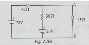
Example
4 Find the voltage across the 15 Ω resistor using
Norton’s theorem for the circuit given below:
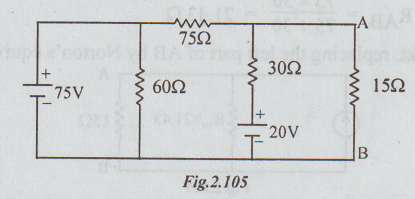
Solution
: Here also since 75V is the ideal voltage source, 60
Ω
resistor can be removed without altering the performance of the circuit. The
resultant figure is re-drawn as below:
Step
1: To find Norton's current ISC :
Short circuit terminals A and B, as a result of which the circuit becomes as
below:

Step
2: To find RTh:
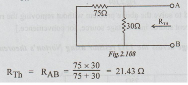
Step
3: In the original ckt, replacing the left part of AB
by Norton's equivalent we get,

Example
5 Obtain Norton's equivalent across terminals A and B for the network shown below:

Solution:
Step 1: To calculate ISC :
Short-circuit terminals A and B to obtain the following circuit.
Since
the capacitor is short circuited there is no current flow through it. The
source current is divided into two parallel paths. A part of I flows through
series combination of 20 and 30 which is also ISC. Remaining of I flows through
j15 Ω.
Step
2: To find ZTh: From the original
circuit kill the energy source. i.e., Open circuit current source.
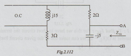
Between
the terminals A and B there are two branches in parallel. The impedance of one
branch is Z1= 5 + j 15.
The
impedance of the other =

Step
3 : Norton’s equivalent circuit is
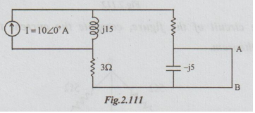
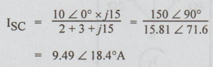
Example
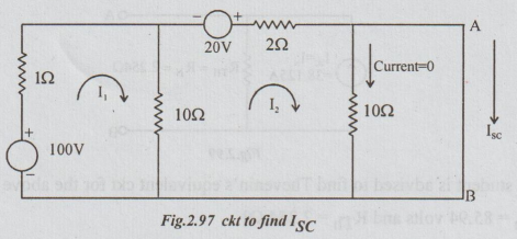
6 In the circuit of the figure, compute the current through the O resistance
ammeter. Use Norton’s theorem.

Solution
:
Step
1 : To find ISC : For this we have to
short circuit the terminals A and B. As the resistance of the ammeter is O(RL =
0), we can make use of the given circuit itself to find ISC.
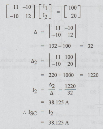
ISC
= I1 ~ I2
By
inspection,

Step
3:
Norton's equivalent circuit
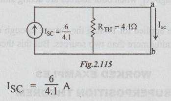
ISC
= 6/4.1 A
[Note:
The current through the zero resistance ammeter is ISC which was found by
loop current method. There is no need of RTh. But to let the student to know as
how to apply Norton's theorem through a short circuited path, the problem is
solved by this method.]
Electric Circuit Analysis: Unit II: Network Reduction and Theorems for dc and ac Circuits : Tag: : - Solved Example Problems: Thevenin's, Norton's Theorem
Related Topics
Related Subjects

Electric Circuit Analysis
EE3251 2nd Semester 2021 Regulation | 2nd Semester EEE Dept 2021 Regulation