Electric Circuit Analysis: Unit II: Network Reduction and Theorems for dc and ac Circuits
Solved Example Problems
DC and AC Circuits Network Reduction Using Theorems
1. Thevenin's Theorem, 2. Norton's Theorem, 3. Super Position Theorem, 4. Maximum Power Transfer Theorem, 5. Reciprocity Theorem, 6. Milliman's Theorem
1. Thevenin's Theorem,
2. Norton's Theorem,
3. Super Position Theorem,
4. Maximum Power Transfer Theorem,
5. Reciprocity Theorem,
6. Milliman's Theorem
1. THEVENIN'S THEOREM -
Example 1 Determine the current I in the network by using Thevenin's theore
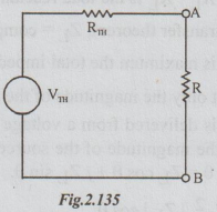
Solution: Step 1. The Thevenin's equivalent circuit is

Step 2: To find VTh: From the given circuit disconnect RL = 10 Ω

Step 3: To calculate RTh: From the above circuit, kill the sources. The resultant circuit is

Example 2 Find the Thevenin's equivalent for the network of the figure between a and b.
Solution: The network given is a combination of voltage and current sources. By converting voltage source into current source and vice-versa, wherever necessary and simplifying we can obtain the required network.
Step 1: Converting or transforming the voltage source of 10V in series with resistance 32 into equivalent current source, the following circuit is obtained.

Step 2: Replacing the 2 current sources in parallel by its equivalent current source, we get the following circuit.
Step 3: Transforming the 2 current sources in series by their equivalent voltage sources we get the following network.

Step 4: Transforming the voltage sources which are parallel in the above circuit, into their equivalent current sources we get the following network.

Step 5: Converting the current source into equivalent voltage source, we get the Thevenin's equivalent circuit as shown below:
Note: From step 3, we can proceed to find VTh and RTh without going through step 4.
Example 3 Calculate, using Thevenin's theorem the current through the branch FC.
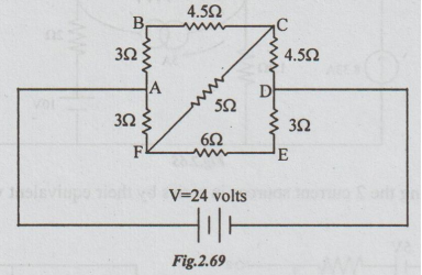
Solution: Step 1: The Thevenin's equivalent circuit is,

Step 2: To calculate VTh:
Disconnect RL = 5 Ω, between F and C terminals.
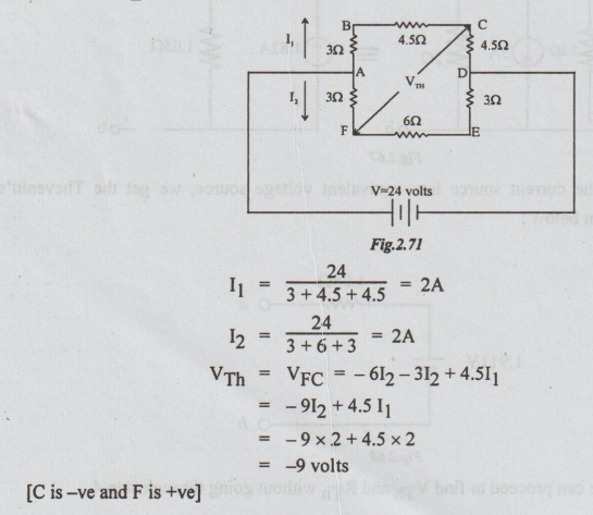
Step 3: To calculate RTh: Re-draw the above circuit, after killing the voltage source.

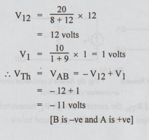
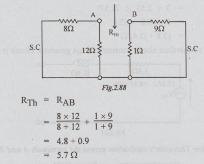
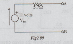
Example 4 It is required to find current through the 0.12 resistor in the figure, using Thevenin's method.
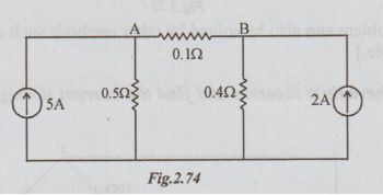
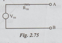
Solution: Step 1: The Thevenin's equivalent circuit :
Solution: Step 2: To calculate VTh: From the given network disconnect (remove) RL = 0.1 Ω
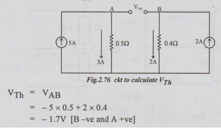
VTh = VAB
= -5 × 0.5 + 2 × 0.4
= -1.7V [B-ve and A +ve]
Step 2: To calculate RTh: Kill the current source in the above circuit by open circuit (O.C.)
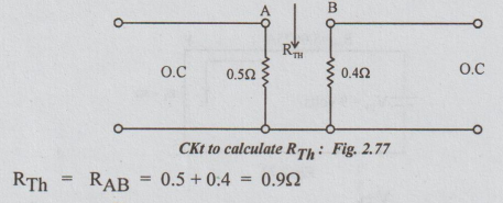
Step 3:

[Note: The above problem can also be solved by other methods such as source conversion method and superposition principle.]
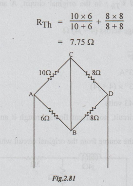
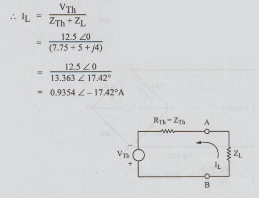
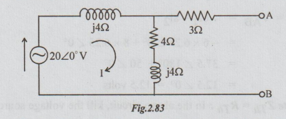
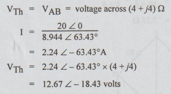
Example 5 Use Thevenin's theorem and find the current through (5+ j4) Ω impedance in the figure.
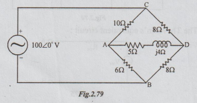
Solution: Step 1: To find VTh: Disconnect ZL = (5+j4) Ω

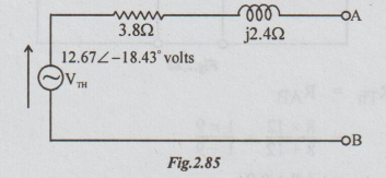
Step 2: To calculate ZTh = RTh: In the above circuit, kill the voltage source, by shorting C and D terminals.
Step 3: Thevenin equivalent ckt
Example 6 Find the Thevenin's equivalent circuit for the network given in the figure.
Solution: Step 1: To find VTh: In the original circuit, A and B terminals are shown open circuited.
[Note: As 3 Ω is in open circuit, no current flows through it and hence no voltage drop occurs across it.]
Step 2: To find ZTh: Kill the source from the original circuit where ZL is already removed.

Step 3: The Thevenin's equivalent circuit constant voltage generator circuit is
Example 7 Determine Thevenin's equivalent across the terminals A and B.

Solution: For clear understanding, let us re-draw the given circuit as shown below:

Step 1: To find VTh: For each loop, there are two resistors in series. By distribution of voltage formula,
Step 2: To calculate RTh: Killing the source in the circuit shown in the fig. above, we get the following passive network.
The Thevenin's equivalent circuit becomes as below:
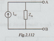
2. NORTON'S THEORM - WORKED EXAMPLES PROBLEMS
Example 1 Determine the voltage across 2002 resistor in circuit by Norton's theorem.
Solution: Step 1: To find the short circuit current ISC. Replace the 200 2 by short circuit. The current through short circuited AB is ISC. Refer the following figure.
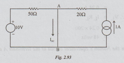
The voltage source will drive a current of 10/50 = 0.2 A, which flows through short circuited AB only. Similarly the current of 1A flows through 20 and then through short-circuited AB only. 0.2 A will not flow through 20 Ω and 1A will not flow through 50 Ω. It is because of short-circuit. So, ISC = 0.2+1= 1.2A.
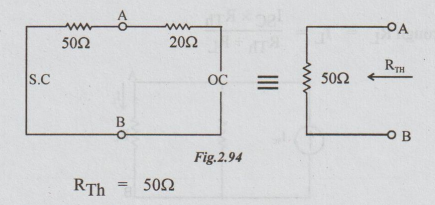
Step 2: To find RTh: From the given circuit, disconnect RL = 200 Ω between A and B and also kill the sources. The resultant circuit becomes as below:
Step 3: Drawing Norton's equivalent circuit and showing the load resistance RL, we get the following circuit:

Example 2 Obtain the Norton's equivalent circuit at the terminals A and B for the network shown.

Solution: Step 1: To calculate ISC: Short circuit A and B terminals to get the following circuit.
As 10 Ω is shorted, no current flows through it. Hence ISC = I2. Neglect presence of 10 Ω. By inspection,
Step 2: To find RTh: From the original circuit kill the sources. Remember that 100 must be taken and it is effective.

Step 3: Norton's equivalent circuit is
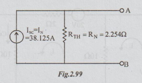
[Note: The student is advised to find Thevenin's equivalent ckt for the above problem.]
[Ans: VTh = 85.94 volts and RTh = 2.254 Ω]
Example 3 Obtain the Norton's equivalent circuit at the terminals A and B for the network shown.
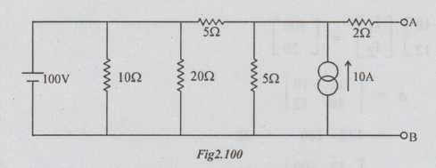
Solution: 10 Ω and 20 Ω are connected across the ideal voltage source. Hence these resistors can be removed without altering the performance of the network. Also converting the current source into voltage source we get the following circuit :

Norton's equivalent can be found for the above circuit by converting the Thevenin's equivalent source into current source. Or, we can directly find the Norton's equivalent which is done as below:
Step 1: To find short-circuit current. Short circuit the terminals A and B to obtain the following circuit:

By loop current method, we can write that
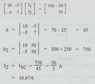
Step 2 : To find RTh : Killing the sources and keeping A and B terminals open, we get

[Note : The student is advised to solve the above problem without removing the resistance of 10 Ω and 20 Ω. He can convert the current source into voltage source, for convenience.]
Example 4 Find the voltage across the 15 Ω resistor using Norton’s theorem for the circuit given below:
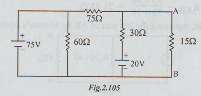
Solution : Here also since 75V is the ideal voltage source, 60 Ω resistor can be removed without altering the performance of the circuit. The resultant figure is re-drawn as below:
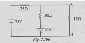
Step 1: To find Norton's current ISC : Short circuit terminals A and B, as a result of which the circuit becomes as below:

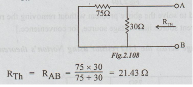
Step 2: To find RTh:
Step 3: In the original ckt, replacing the left part of AB by Norton's equivalent we get,

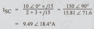
Example 5 Obtain Norton's equivalent across terminals A and B for the network shown below:

Solution: Step 1: To calculate ISC : Short-circuit terminals A and B to obtain the following circuit.
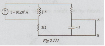
Since the capacitor is short circuited there is no current flow through it. The source current is divided into two parallel paths. A part of I flows through series combination of 20 and 30 which is also ISC. Remaining of I flows through j15 Ω.
Step 2: To find ZTh: From the original circuit kill the energy source. i.e., Open circuit current source.
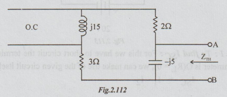
Between the terminals A and B there are two branches in parallel. The impedance of one branch is Z1= 5 + j 15.
The impedance of the other =

Step 3 : Norton’s equivalent circuit is
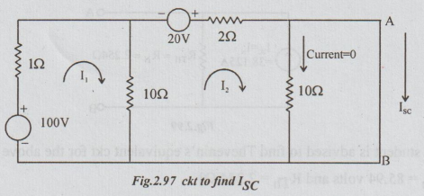
Example 6 In the circuit of the figure, compute the current through the O resistance ammeter. Use Norton’s theorem.

Solution :
Step 1 : To find ISC : For this we have to short circuit the terminals A and B. As the resistance of the ammeter is O(RL = 0), we can make use of the given circuit itself to find ISC.
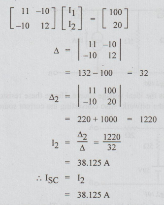
ISC = I1 ~ I2
By inspection,

Step 3: Norton's equivalent circuit
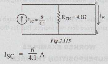
ISC = 6/4.1 A
[Note: The current through the zero resistance ammeter is ISC which was found by loop current method. There is no need of RTh. But to let the student to know as how to apply Norton's theorem through a short circuited path, the problem is solved by this method.]
3. SUPERPOSITION THEOREM - WORKED EXAMPLES
Example 1 Compute the current through 23 ohm resistor of the figure below by using superposition theorem.
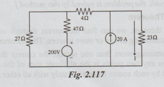
Solution: Step 1: Allow only the voltage source to act. The corresponding circuit is as below:

The resistance connected to the source = 47 + 27 × 27 / 27+ 27
= 60.5 ohms
Total current from the source = 200 / 60.5 = 3.306 A
The current through 23 ohms = IL = 3.306 × 27
= 1.653 A
Step 2: Allow only the current source to act. The circuit becomes as
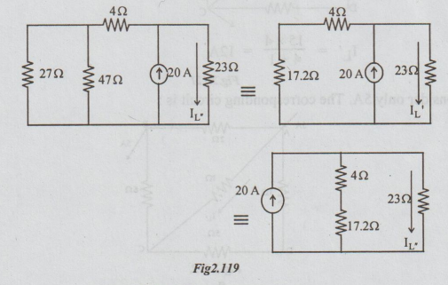
IL = 20 × 21.2 / 21.2 + 23 = 9.6 A
By superposition theorem, IL = IL + IL “ = 1.653 + 9.6 = 11.253 A
[Note: The directions of IL' and IL
Example 2 Using superposition theorem, find the current in resistance R3 in the circuit shown below.
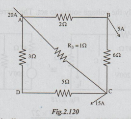
Solution: The above circuit diagram may be assumed to be consisting of two currents. One current of 15 A entering at A and leaving at C. Another current of 5A, entering at A and leaving at B.
Step 1: Consider only 15A. The relevant circuit diagram is as below:
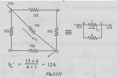
Step 2: Consider only 5A. The corresponding circuit is:

1Ω and 8Ω are in parallel. Their equivalent is 8/9 = 0.9Ω 0.9Ω and 6Ω are in series, equal to 6.9Ω.

Example 3 Find the current in the 22 resistor between A and B for the network using superposition theorem.

Solution: Step 1: When only 10V source is acting:
Let the current through 202 be IL'. The circuit diagram with 10V source acting, and 20V source killed is as below:
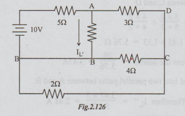
Between B and C, 2Ω and 4Ω are in parallel. Their equivalent = 2 × 4 / 2 × 4 = 1.33 Ω. Now, the circuit diagram can be re-drawn as below:

For the above circuit, the total resistance connected to the 10V source = 5 + 2 × 4.33 / 2 + 4.33 = 6.37 Ω.
Current from the source = 10 / 6.37 = 1.5 A
Therefore IL' = 1.57 × 4.33 / 2 + 4.33
= 1.07 A
Step 2: Allow only 20V source to act, killing the other source. The circuit becomes as :
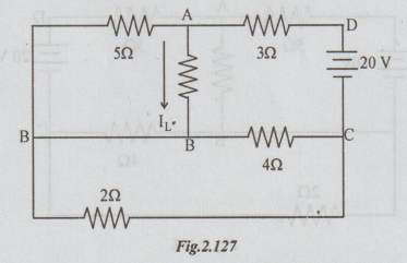
By inspecting the above figure, we can say that across the voltage source 20V, there is series parallel combination of resistances.
Between A and B, 2022 and 502 are in parallel. Between B and C 42 and 202 are in parallel. So, the equivalent resistance between C and D
= 3 + (5 × 2/ 5 + 2) +( 4 × 2 / 4 + 2)
= 3 + 1.43 + 1.33 = 5.76 Ω
The current from the source = 20 / 5.76 = 3.47A
This current is divided into two parallel paths between A and B.
Therefore IL" = 3.47 × 5 / 5 + 2 = 2.48 A
By applying superposition theorem, the current through 2 Ω connected between A and B = IL = IL' +IL' = 1.07 + 2.48 = 3.55A.
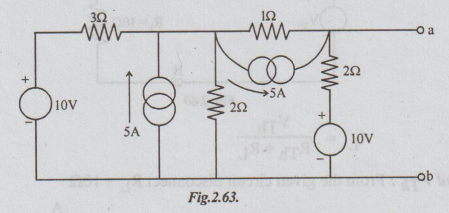
Example 4 Find the current in the branches A, B, C of the following 2 source network. Apply superposition principle.

Solution: Step 1: When only V source is acting, I source becomes open circuit. Refer fig .2.128 (b). The current from V source flows only through 2Ω and 2Ω. No current flows through 4Ω as open circuit
I1 = 4 / 2 + 2 = 1A.
Step 2: Allow only the I source to act, then V source becomes short circuited. For circuit refer fig.2.66 (c). The source current of 2A flows through 42 and is divided into two paths. The currents shown in the figure are
Iɑ = 2 × 2 / 2 + 2
Ic = 2 - 1 = 1A
By applying superposition principle,
Current through branch A = I1 - 1ɑ = 1 -1 = 0
Current through branch C = I1 + Ic = 1 + 1 = 2A
Current through branch B = 2A
Example 5 Using superposition theorem or otherwise, obtain the current in EA in figure below:

Step 1: First allow only IV source to act. Let the current in EA be I'. The relevant circuit diagram is as below:
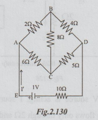
I' can be found by applying mesh current method or converting delta to star and then applying Ohm's law. The above circuit becomes as drawn below after converting delta connection between A, B and C into its equivalent star.
Total resistance connected across the source
= 0.75 + 5 × 8 / 5 + 8 + 10 = 13.83 Ω
I’ = voltage / resistance = 1/13.83
= 0.0723 A = 72.3 mA
It flows from E to A.
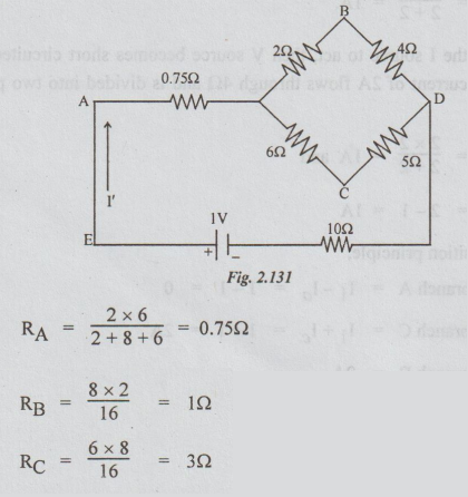
Step 2: When only 2V source is acting and the other source short circuited, the circuit becomes as shown in fig. 2.131. Now let the current in EA be I".
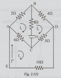
For the calculation of I", loop current method is applied. Let the loop currents be 11, 12 and 13 as shown in the figure above. I" = I1.

Step 3: By applying superposition theorem, the current through
EA = I = I' + 1'= 72.3 - 9.736 = 62.564 mA.
4. MAXIMUM POWER TRANSFER - SOLVED EXAMPLE PROBLEMS
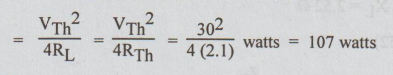
Example 1 The circuit shown in the figure, R absorbs maximum power. Compute the value of R and maximum power.
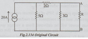
Solution: Thevenin's equivalent circuit is drawn as below :
To find VTh: Disconnect R from the original circuit.
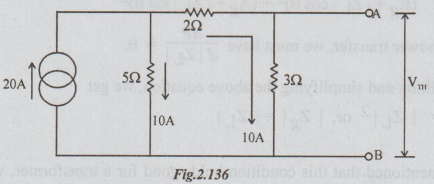
VTh = VAB = -10 × 3 = - 30 volts
= 30 volts [with B negative and A positive]
To find RTh: From the above circuit, open circuit the current source. Thus,
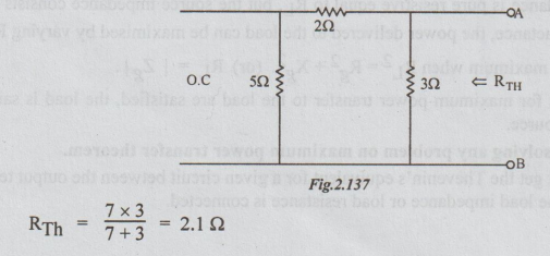
According to the statement of maximum power transfer theorem, the value of R for maximum power transferred to it = RTh = 2.1 Ω and the maximum power transferred
Example 2 A loud speaker is connected across the terminals A and B of the network shown in figure below. What should be the value of impedance of the speaker to obtain maximum power transferred to it and what is the maximum power?

Solution: The Thevenin's equivalent circuit is as shown above.
To find VTh: In the original circuit the current
To find ZTh: From the original circuit, killing the voltage source, the following circuit is obtained.

For maximum power transfer, let the load impedance be ZL = RL + j XL, both being variables.

Example 3 For the circuit of the figure, find the value RL for maximum power delivered to it. Calculate also the maximum load power.

Solution: Step 1: To find VTh: Disconnect RL between A and B terminals.
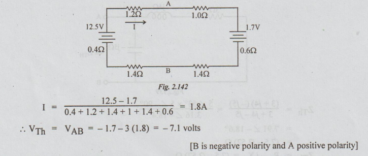
[B is negative polarity and A positive polarity]
Step 2: To find RTh: Kill the sources from the circuit in the step 1 to get the following circuit.

Step 3: Thevenin's equivalent circuit is drawn as below:

From this, we can say that the values of RL for maximum power transferred to it

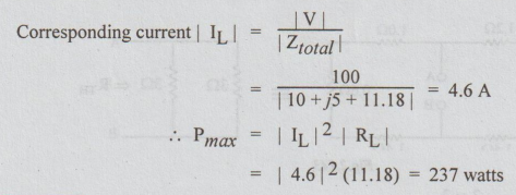
Example 4 In the circuit of fig. below, find the value of RL which results in maximum power and calculate the value of maximum power.

Solution: From the given circuit, the value of RL for maximum power transferred to it = | Zg | = | 10 + j5 | = 11.18 Ω.
Example 5 A 1 KHz generator has an internal impedance containing a resistance of 502 in series with and inductance of 0.01 H. It is supplying a load of 1000 Ω resistance. A capacitor is connected in parallel with the load and a circuit of inductance L and negligible resistance is put in series with the generator. Find the values of C and L which will give maximum power in the load.
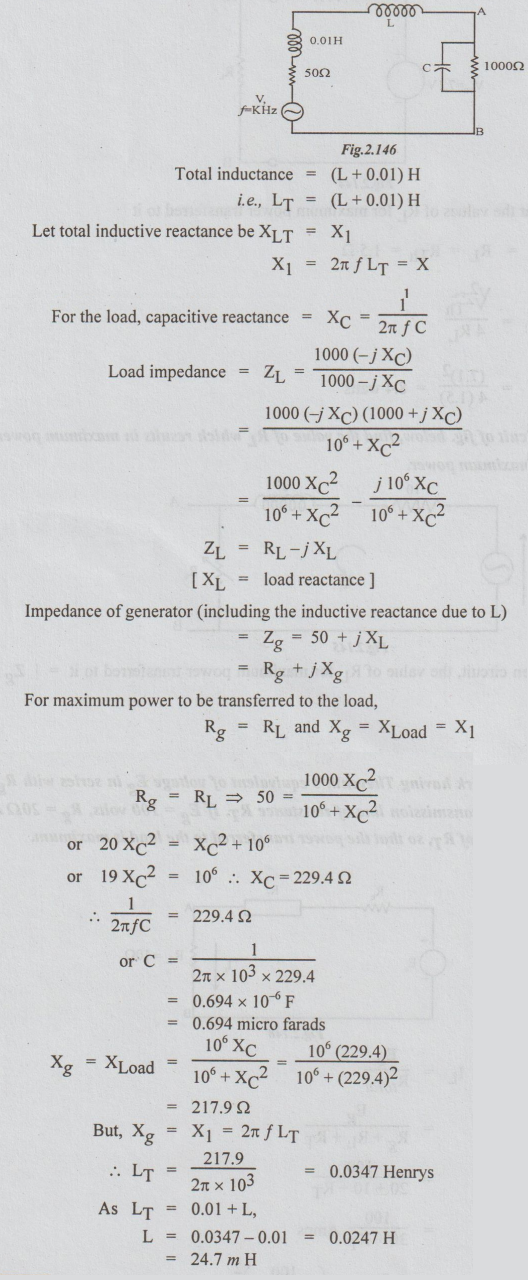
Example 6 A load impedance of (20 - j XC) Ω is supplied from a source of e.m.f. 10V r.m.s. and internal impedance (10 + j20) Ω Find the value of Xc to give maximum power dissipation in the load and calculate the value of this power.

Solution: If the load resistance as well as load reactance are variables, the load must be conjugate of the source impedance for maximum power transfer. If the reactance alone is variable, the load reactance = source reactance, with opposite nature. Hence XC = 20Ω.
Total impedance = Ztotal

Example 7 A network having Thevenin's equivalent of voltage Eg in series with Rg supplies a load of RL through a transmission line of resistance RT. If Eg = 100 volts, Rg = 202 and RL = 10Ω, determine the value of RT, so that the power transferred to the load is maximum.
Solution:

5. RECIPROCITY THEOREM - WORKED EXAMPLES
Example 1 For the circuit shown in the figure below, find 13 and verify reciprocity theorem.
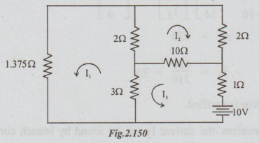
Solution: Step 1: By inspection putting in the matrix form, we get

Step 2: Transferring the battery, to the branch with 1.375 Ω resistor, the following circuit is obtained. The current through 1 Ω is taken as I3. According to reciprocity theorem this I3 = 2A.
Let us calculate the value of I3 in figure below:

Thus reciprocity theorem is verified.
Note: In the above problem, the current 13 can be found by branch current method. In that case both KCL and KVL are to be applied. It is solved here by loop current method, where only KCL is to be applied. This method is preferred to loop current method.
Example 2 Verify reciprocity theorem in the circuit shown in the figure and also calculate the transfer resistance.

Solution: Step 1:
Voltage across 8 ohms = V = Ig × R
But Ig = 10 × 2 / 2 + 8 = 2A
R = 8Ω
V = 2 × 8 = 16V
Step 2: Interchanging the current source and response, the circuit becomes as below: Here the response is V.

V = I2 × R, R = 2Ω, since the current 2
In both cases, the ratio of voltage to current is the same. Hence the reciprocity theorem is verified.
The transfer resistance = V/ I = 16/10 = 1.6Ω
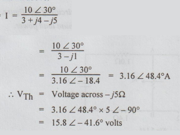
Example 3 In the network shown in the figure, the voltage source 100 ∠ 45°V causes current Ix in the 5Ω branch. Find Ix and then verify the reciprocity theorem for this circuit.
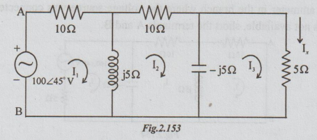
Solution: Step 1: It is required to find the value of Ix. Let us apply loop current method. If the loop currents are taken to be I1, I2 and I3 as shown, then Ix = I3.
For the above circuit, by inspection, we can write that

Step 2: Now connect the voltage source in the branch in which the current is I, i.e., in 52 branch and connect an a.c. ammeter in the branch where the voltage source was connected earlier as shown below. If ammeter is not available, short the terminals A and B.
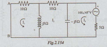
If the current through AB is same as the value of Iy in the step 1, we can say that the reciprocity theorem is verified. To calculate the current let us again prefer loop current method to other methods.
By inspection.

Hence the reciprocity theorem is verified.
Example 4 In the circuit shown determine Vx Then apply the reciprocity theorem and compare the 2 voltages.
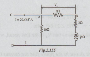
Solution : Step 1 : Vx = I5 × 5
Is is the current through the series combination of 5Ω, 3Ω and j8Ω.
I5 = 20 ∠ 45° × 10 / 10 + 5 + 3 + j8
= 200 ∠ 45° / 19.7 ∠ 23.96°
= 10.15 ∠ 21.04°A
Vx = 10.15 ∠ 21.04° (5 ∠ 0°)
= 50.75 ∠ 21.04° V
Step 2: Connecting the current source across 5 and voltmeter across C and D, the circuit becomes as:
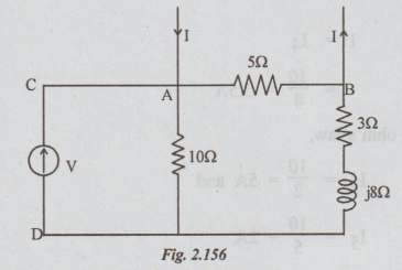
The voltage across CD = V = Voltage across 10Ω
To find the voltage across 10Ω, current through it must be known. As is shown in the circuit, the source current I is divided into two parallel paths. A part of I flows through 5Ωand remaining flows through the series combination of 10Ω, j8Ω and 3Ω.
By current division formula current through 10Ω = I10
= 20 ∠ 45° × 5 / 10 + j 8 + 3 + 5
= 100 ∠ 45° / 18 + j8
= 100 ∠ 45° / 19.7 ∠ 23.96
= 5.075 ∠ 21.04°A
V = 5.075 ∠ 21.04° × 10
= 5.075 ∠ 21.04° volts
As this V in the second circuit is same as that Vx in the first circuit, we can say that the reciprocity x theorem is verified.
Example 5 In the circuit shown in the figure find the current in the 42 resistor. Apply the reciprocity theorem and compare the 2 currents. What change results in the current through 5Ω and 2Ω branches?
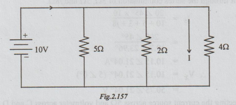
Step 1: In the given circuit, the resistors 402, 22 and 502 are all in parallel across the 10V source. As shown
I = I4
= 10 / 4 = 2.5 A
Similarly by applying ohm's law,
I2 = 10 / 2 = 5 A and
I5 = 10 / 5 = 2A
Step 2: Connecting the voltage source in the 452 branch and D.C. ammeter (of negligible resistance) in place of the voltage source of the given circuit we get the following:
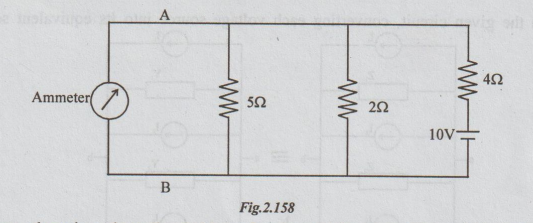
In this figure, there is a short circuit (through ammeter) between the parallel combination of 5Ω and 2Ω. Hence, no current will flow-through 5Ω and 2Ω. The current from the voltage source flows through only 4Ω and the same thing is read by the ammeter. By applying ohm's law, reading of ammeter 10/4 = 2.5A.
Thus, reciprocity theorem is verified for the given circuit.
[Note: After connecting the voltage source in 4Ω resistor, the current through branches of resistances 2Ω and 5 Ω becomes 0.]
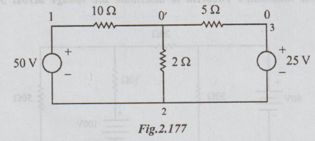
6. WORKED EXAMPLES ON MILLIMAN'S THEOREM
Example
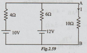
1 Calculate the current I in 42, resistor in the figure using Milliman's
Theorem.
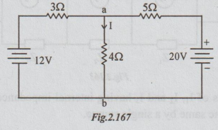
Solution:
Step1:
In the given circuit, the two voltage sources are in parallel, between the
terminals a and b. The circuit can be drawn as below.
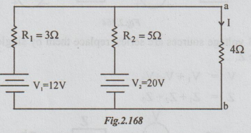
Step
2: This parallel combination can be replaced by a
single source, say of voltage V and internal resistance RΩ.

Step
3: For fig(3b), connect the resistor 42, between a and
b, to obtain the following figure.
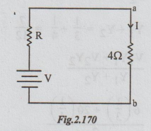
Step
4: For the figure above apply Ohm's law. Then
I
= V / R + 4 = 15 / 1.875 + 4
I
= 2.553 A
Example
2 Use Milliman's Theorem to find the voltage across the terminals A and B and
also the current through RL = 5Ω

Solution:
Step1:
The two voltage sources are in parallel. First let us replace them by a single
voltage source as shown below.
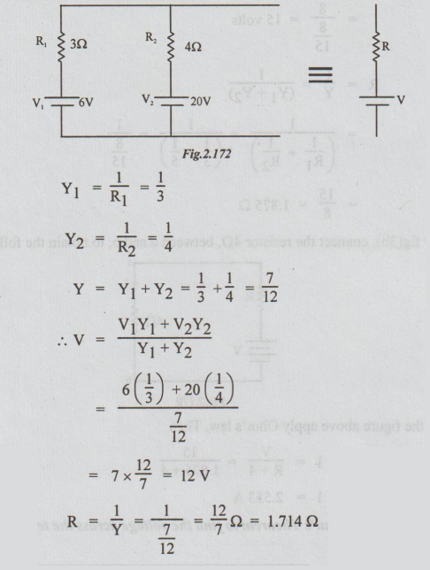
Step
2: Connecting this single voltage source across the
parallel combination of 6Ω & 5Ω, we get

Generalised
form of the Milliman's Theorem:
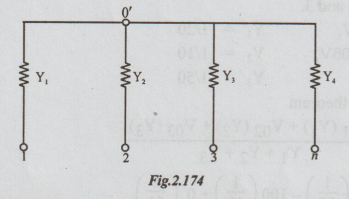
Consider
a number of admittances Y1, Y2, .........Yn,
terminating at a common point 0'. The other ends of the admittances are
numbered as 1,2,3...........n. Let '0' be any other point in the network.
Let
V ∞
= Voltage drop from 0 to 0'
Then
V ∞ =
Vo1Y1 + V02 Y2 +.........+ V0n
Yn / Y1+ Y2 + …. + Yn
Note:
Only those resistances or admittances terminating at the common point are taken
into consideration. Other admittances which do not terminate at the common
point are ignored, even if they are connected in the circuit.
Example
3 Use Milliman's Theorem to determine the voltage across 502 resistor in the
network shown.
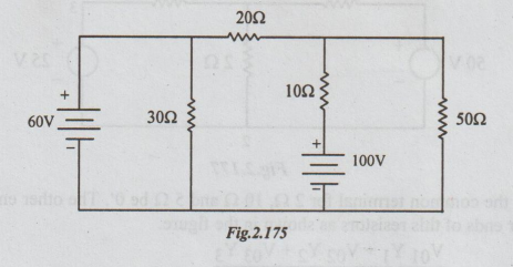
Solution:
Step
1: The given network is redrawn below. Let the
terminals of 502 be 0 and 0' as shown.

Step
2: 2Ω, 10 Ω and 50 Ω are connected to common point 0'.
Let the other ends of these so resistors be marked as 1, 2 and 3.
V01
= 60V, Y1 =
I/20
V02
= - 100V Y2 =
1/10
V03
= 0, Y3 =
1/50
Step
3: By Milliman's theorem
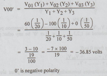
Note:
30 Ω is not directly connected to the common point 0'. Hence it is ignored.
Example
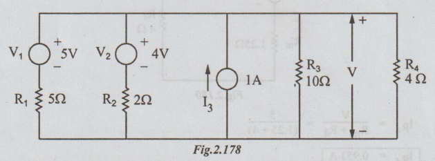
4 Find the current through 5 Ω by applying
the Milliman's theorem.
Solution:
Let the common terminal for 2 Ω, 10 Ω and 5 Ω be 0'. The other end of 5 Ω is 0. 1,
2, and 3 are the other ends of this resistors as shown in the figure.

So
by Ohm's law the current through 5 Ω = 12.5 / 5 = 2.5 A
Example
5 Using Milliman's theorem, find the voltage across 5
Ω and hence current through
Solution:
First, the current source of 1A and 10 Ω is converted into voltage source.

0'
and 0 are the terminals across which 4 Ω are connected.
1,
2 and 3 are the terminals of R1, R2 and R3 Ω
respectively.
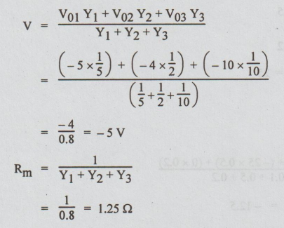
The
left part of R4 Ω is replaced by a single voltage source of voltage
V and resistance Rm. It results in the following circuit.

Example
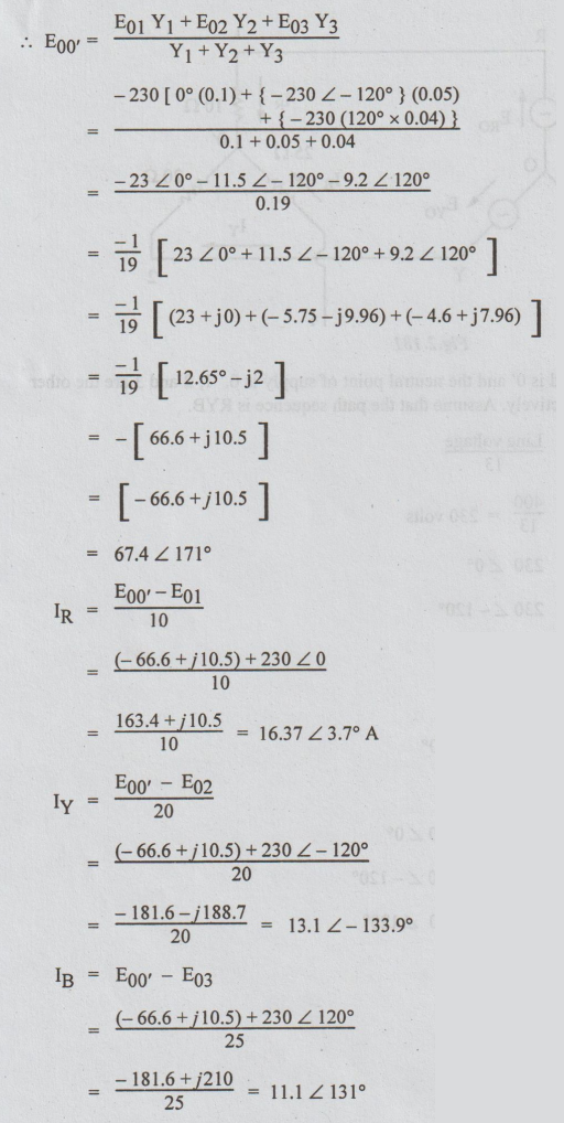
6 Non-reactive resistors of 10, 20, 25 ohms are star connected to the R, Y, B
phases of a 400V symmetrical system. Determine the current in each resistor and
the voltage between star point and neutral. Apply Milliman's theorem.’

Solution:
The star point of load is O' and the neutral point of supply is 0. 1, 2 and 3
are the other ends of 10 Ω ,20 Ω and 25 Ω respectively. Assume that the path
sequence is RYB.
Phase
voltage = Line voltage / 13
=
400 / 13 = 230 volts
ERO
= 230 ∠ 0°
EYD
= 230 ∠ 120°
EBO
= 230 ∠ 120°
EOR
= -230 ∠ 0°
EOY
= -230 ∠ -120°
EOB
= -230 ∠ 120°
E01
= EOR = -230 ∠ 0°
E02
= EOB = -230 ∠ -120°
E03
= EOB = -230 ∠ 120°
Y1
= 1/10 = 0.1
Y2
= 1/20 = 0.05
Y3
= 1/25 = 004
Electric Circuit Analysis: Unit II: Network Reduction and Theorems for dc and ac Circuits : Tag: : DC and AC Circuits Network Reduction Using Theorems - Solved Example Problems
Related Topics
Related Subjects

Electric Circuit Analysis
EE3251 2nd Semester 2021 Regulation | 2nd Semester EEE Dept 2021 Regulation