Electric Circuit Analysis: Unit II: Network Reduction and Theorems for dc and ac Circuits
Thevenin's Theorem
Statement, Circuit Diagram, Equation, Steps, Calculation, Solved Example Problems
Suppose that the current through the load resistance R is required. It can be calculated by the following methods. (a) Series parallel simplification (b) Branch current method (c) Loop current method
NETWORK THEOREMS
1. Thevenin's Theorem
Consider
the following active circuit.
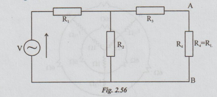
Suppose
that the current through the load resistance R is required. It can be
calculated by the following methods.
(a)
Series parallel simplification
(b)
Branch current method
(c)
Loop current method
If
the circuit consists of one more loop, in addition to the existing two loops,
the first method will become more tedious. If RL takes various
values, whatever method you are applying it will be some what much laborious.
For example, if you apply loop current method, we must form the matrix and
solve for IL. This procedure is to be repeated as many times as the
values of RL. The Thevenin's theorem helps us to avoid the repeated
procedure. By this theorem we can replace a given active circuit between two
terminals by a constant voltage source.
Then,
by applying ohm's law, we can compute the value of IL.
Statement
of Thevenin's Theorem :
Any
linear active network with output terminals A and B as shown in fig. 2.57 (a)
can be replaced by a single voltage source (VTh= Voc) in series with
a single impedance (ZTh = Zi)
VTh
is the Thevenin's voltage. It is the voltage between the terminals A and B on
open circuit condition. Hence it is called open circuit voltage denoted by Voc
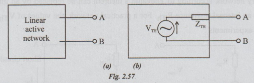
ZTh
is called Thevenin's impedance. It is the driving point impedance at the
terminals A and B when all internal sources are killed. In case of D.C, ZTh
is replaced by RTh
If
a load impedance ZL is connected across AB, we can find the current
through it by the formula
IL
= VTh / ZTh+ZL
Note:
1. This theorem can be applied for both D.C and A.C circuits.
2.
In the Thevenin's equivalent circuit (Voltage source), if AB terminals are
short circuited, the current flowing through AB is obtained by ohm's law. Refer
fig. 2.93 (b).
Isc
= VTh / ZTh ⇒
ZTh = VTh / ISC
Steps
to be followed in applying Thevenin's Theorem
The
following steps are necessary in applying Thevenin's theorem for the given
network:
1.
Let the load resistance be RL through which the current IL
is required. Mark the terminals A and B (for convenience) across which RL is
connected. i.e., RL is supposed to be connected between the
terminals marked as A and B.
2.
Blindly, draw the Thevenin's equivalent circuit between A and B terminals. It
is a constant voltage source with voltage VTh and resistance RTh
3.
In the given circuit disconnect RL and redraw the fig. after removing
RL. Find the voltage or br between A and B. It is VTh
4.
From the circuit in the above step, kill all the energy sources properly and
obtain the equivalent resistance between A and B when looked back. It is RTh
RTh
can also be calculated in the following way:
(a)
In a given circuit, replace RL by short-circuit. Find the current
through this. It is ISC.
So,
RTh = VTh / ISC
Open
and Short Circuit Method for finding Internal Z (Zi
= ZTh)
of a network
Every
network according to Thevenin's theorem can be replaced by an internal source VTh
in series with an internal resistance RTh. For a practical network,
the values of VTh and RTh may be found by two
experiments:
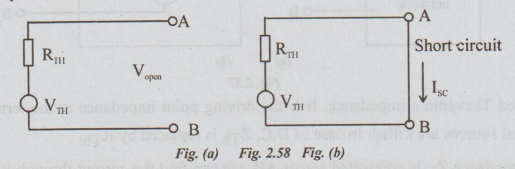
1.
Keep the terminals open as shown in fig.2.58 (a). The voltage between the open
terminals A and B is VTh. It can be measured with a high resistance
voltmeter, connected across the terminals.
2.
Short circuit the terminals and connect an ammeter in series with the
short-circuit. Refer fig. (b). The ammeter measures the short-circuit current ISC.
As the resistance of the meter is negligible, the ammeter does not affect the
conditions of a short-circuit.
From
fig. (b), ISC = VTh / RTh (by ohm's law)
Therefore,
RTh = VTh / ISC = open circuit voltage / short
circuit current
These
two tests are the ones which are generally employed to determine the network
equivalent of electric machines such as transformer, alternator, induction
motor and so on.
Power
Calculation using Thevenin's Theorem
We
have seen that this theorem replaces an active network by a voltage VTh
and a series resistance RTh, as far as any external load connected to the
terminals of the network is concerned. For instance, if the load current is IL,
then the power dissipated in RL will be I2L
RL. As IL is actual current, the power calculated will also be
correct. That means, the theorem can be used to find the power in external
circuit.
In
the Thevenin's equivalent there is no current flow when the terminals are open.
So, the internal power is 0. But in the actual network, even when the terminals
are open, currents may flow because of some closed loops. Hence, there is power
loss. We may call it no load power loss. The power calculations are true
externally but not internally.
The
power loss in the actual network and in its Thevenin's equivalent are not
equal. But, the difference between the two losses is constant. It does not vary
with change in the external load. The constant difference is the no-load power
loss.
BOOT WORKED EXAMPLES
THEVENIN'S THEOREM
Example 1 Determine the current I in the network by using Thevenin's theore
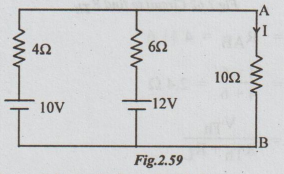
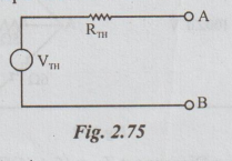
Solution: Step 1. The Thevenin's equivalent circuit is

Step 2: To find VTh: From the given circuit disconnect RL = 10 Ω

Step 3: To calculate RTh: From the above circuit, kill the sources. The resultant circuit is

Example 2 Find the Thevenin's equivalent for the network of the figure between a and b.
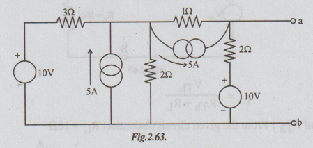
Solution: The network given is a combination of voltage and current sources. By converting voltage source into current source and vice-versa, wherever necessary and simplifying we can obtain the required network.
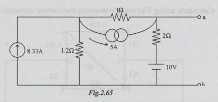
Step 1: Converting or transforming the voltage source of 10V in series with resistance 32 into equivalent current source, the following circuit is obtained.

Step 2: Replacing the 2 current sources in parallel by its equivalent current source, we get the following circuit.
Step 3: Transforming the 2 current sources in series by their equivalent voltage sources we get the following network.

Step 4: Transforming the voltage sources which are parallel in the above circuit, into their equivalent current sources we get the following network.

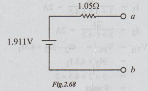
Step 5: Converting the current source into equivalent voltage source, we get the Thevenin's equivalent circuit as shown below:
Note: From step 3, we can proceed to find VTh and RTh without going through step 4.
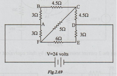
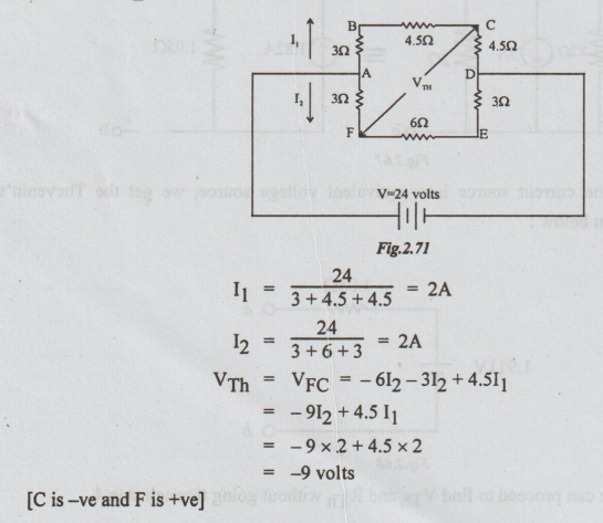
Example 3 Calculate, using Thevenin's theorem the current through the branch FC.
Solution: Step 1: The Thevenin's equivalent circuit is,

Step 2: To calculate VTh:
Disconnect RL = 5 Ω, between F and C terminals.
Step 3: To calculate RTh: Re-draw the above circuit, after killing the voltage source.

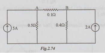
Example 4 It is required to find current through the 0.12 resistor in the figure, using Thevenin's method.
Solution: Step 1: The Thevenin's equivalent circuit :
Solution: Step 2: To calculate VTh: From the given network disconnect (remove) RL = 0.1 Ω
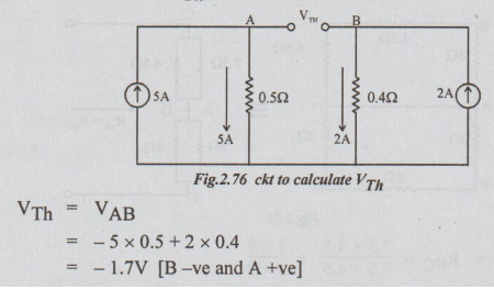
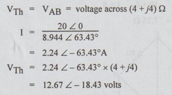
VTh = VAB
= -5 × 0.5 + 2 × 0.4
= -1.7V [B-ve and A +ve]
Step 2: To calculate RTh: Kill the current source in the above circuit by open circuit (O.C.)
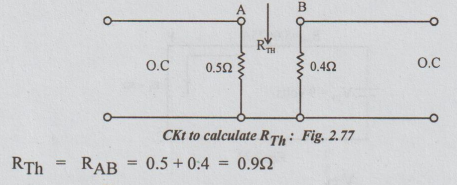
Step 3:

[Note: The above problem can also be solved by other methods such as source conversion method and superposition principle.]
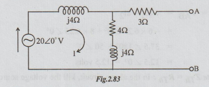
Example 5 Use Thevenin's theorem and find the current through (5+ j4) Ω impedance in the figure.
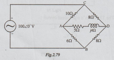
Solution: Step 1: To find VTh: Disconnect ZL = (5+j4) Ω

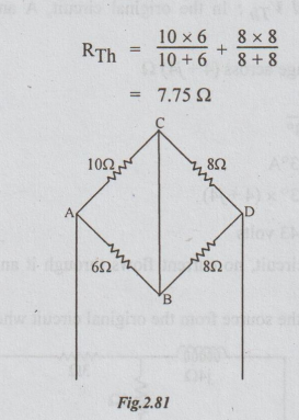
Step 2: To calculate ZTh = RTh: In the above circuit, kill the voltage source, by shorting C and D terminals.
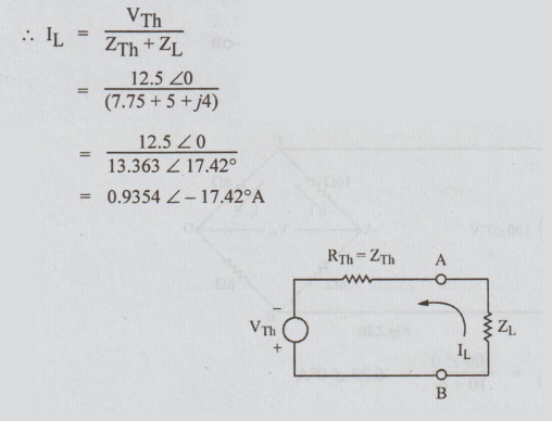
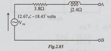
Step 3: Thevenin equivalent ckt
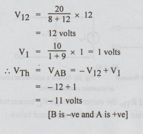
Example 6 Find the Thevenin's equivalent circuit for the network given in the figure.
Solution: Step 1: To find VTh: In the original circuit, A and B terminals are shown open circuited.
[Note: As 3 Ω is in open circuit, no current flows through it and hence no voltage drop occurs across it.]
Step 2: To find ZTh: Kill the source from the original circuit where ZL is already removed.

Step 3: The Thevenin's equivalent circuit constant voltage generator circuit is
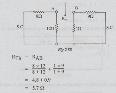
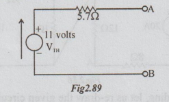
Example 7 Determine Thevenin's equivalent across the terminals A and B.

Solution: For clear understanding, let us re-draw the given circuit as shown below:

Step 1: To find VTh: For each loop, there are two resistors in series. By distribution of voltage formula,
Step 2: To calculate RTh: Killing the source in the circuit shown in the fig. above, we get the following passive network.
The Thevenin's equivalent circuit becomes as below:
Electric Circuit Analysis: Unit II: Network Reduction and Theorems for dc and ac Circuits : Tag: : Statement, Circuit Diagram, Equation, Steps, Calculation, Solved Example Problems - Thevenin's Theorem
Related Topics
Related Subjects

Electric Circuit Analysis
EE3251 2nd Semester 2021 Regulation | 2nd Semester EEE Dept 2021 Regulation