Transmission and Distribution: Unit V: (b) Substations and Grounding
Ungrounded or Isolated Neutral System
Question : 1. Explain ungrounded or isolated neutral system.
Ungrounded or Isolated
Neutral System
As the name indicates, the system
neutral is not connected to the earth in this system. Thus the neutral is
isolated from the earth. A simple isolated neutral system is shown in the Fig.
8.12.1 (a).
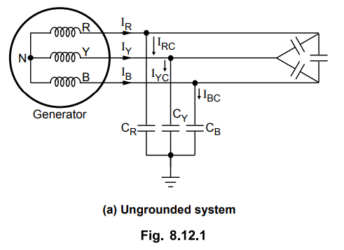
There is always capacitive coupling
between conductors and earth which causes capacitive currents to flow in the
the system. The line conductors have capacitance between one another and to
earth. The capacitance between conductors is represented in delta while
capacitance between conductor and earth is in star for 3 phases. As the
grounding characteristics of the system are little affected by line
capacitances, they can be neglected.
The capacitance to earth of each phase
is uniformly distributed along its entire length and for all the calculations
this capacitance is grouped to form a single capacitor connected between each
phase and earth. These currents lead their respective voltages by 90° as shown
in the phasor diagram. Fig. 8.12.1 (b).

For a perfectly transposed line
(symmetrically spaced) the capacitive currents IRC, IYC and IBC are equal in
magnitude and displaced from each other by an angle of 120°. In balanced load
condition with symmetrical spacing between conductors, the potential of neutral
will be equal to that of earth as shown in the Fig. 8.12.2.

The charging currents IRC, IYC
and IBC are balanced and their resultant is zero and no current
flows to the earth. Now let us consider the earth fault on Y phase say at point
P. The corresponding phase will be at earth potential while the remaining
healthy phases acquire line value from phase value as shown in the Fig. 8.12.3.
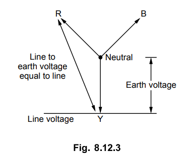
The capacitive current will not flow in this phase. The potential of neutral is not zero but it is shifted from earth potential position to position shown in the Fig. 8.12.3.
The circuit diagram and the
corresponding phasor diagram during the fault is as shown in the Fig. 8.12.4.

Under fault condition, the capacitive
currents are imbalanced and the fault current flows through the faulty line,
into the fault and returns to the system via earth and through the earth
capacitances CR and CB. The current in Y line has two
components one IRC and other IBC and the respective
voltages driving these currents are VRY and VYB and the
phase difference between currents and voltages is 90° due to capacitive nature
of the impedance of the circuit. The vector sum of IRC and IBC gives fault
current IF.
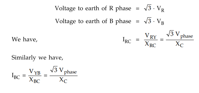
Both Vphase and XC
are equal and the fault current is given by vector sum of IRC and IBC
as shown in the Fig. 8.12.5.
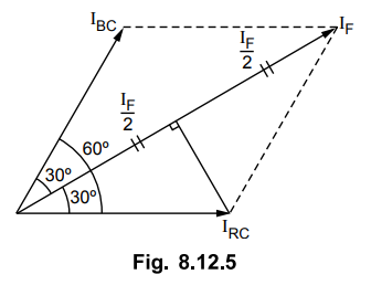
From the diagram,
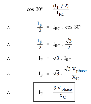
From the above equation, it can be seen
that the current flowing through faulty phase is three times the normal line to
neutral capacitive current flowing in each phase of the healthy system.
The following observations can be seen
from the above analysis
1. With an ungrounded neutral system, if
there is phase to earth fault then the voltages of the healthy phases with
respect to earth rise from normal phase to neutral value towards full line
value which may result in insulation breakdown.
2. The capacitive current in the
remaining healthy phases increases to V3 times its normal value.
3. The capacitive current in the faulty
phase is √3 times its normal value.
4. A capacitive current flows into the
earth. If its magnitude is in excess of 4 to 5 amperes then it is sufficient to
maintain an arc in the ionized path of the fault. This current can remain even
after clearance of fault. This phenomenon of persistant arc is called arcing
ground. The system capacity will be charged and discharged in cyclic order due
to which high frequency transients may occur which will cause high voltages of
the order of 5 to 6 times the normal value may be present which results in
insulation breakdown. This may cause another line to line fault because of
insulation breakdown either on same circuit or on another circuit. Thus a minor
fault also results in insulation breakdown and interruption of supply.
Due to imbalance in capacitive currents
during fault, discriminative type of fault indicator can not be installed. But
the neutral shift indicator may be inserted in the system which only indicates
the occurrence of earth fault but does not give its location.
The advantages of isolated neutral
includes the operation of the system with single line to ground fault. Also the
radio interference is minimized due to absence of zero sequence currents.
In summary, the ungrounded system does
not provide protection against earth fault to adequate level with chances of
insulation breakdown because of which a phase to phase fault may occur. Due to
all these reasons this system is not commonly used in practice now a days. The
earthed relay system has many advantages due to which it is preferred in modem
power system installations.
Review Question
1. Explain ungrounded or isolated neutral system.
Transmission and Distribution: Unit V: (b) Substations and Grounding : Tag: : - Ungrounded or Isolated Neutral System
Related Topics
Related Subjects

Transmission and Distribution
EE3401 TD 4th Semester EEE Dept | 2021 Regulation | 4th Semester EEE Dept 2021 Regulation