Digital Logic Circuits: Unit V: VHDL
VHDL Description for Finite State Machines (FSM)
1. VHDL Code for Mealy-Type State Machines 2. VHDL Code for Moore-Type State Machines
VHDL Description for Finite State Machines (FSM)
•
A VHDL description of a state machine can be written using communicating
concurrent processes for the following components.
1.
Combinational Component
•
This component can be implemented within one process. Being a combinational,
this process is sensitive to events on the input signals and changes in the
state. So whenever there is a change in any of the input signals or the state
variables, this process is executed and computes new values for the output
signals and the new state variables.
2.
Sequential Component
•
This component can be implemented within a second process. Being a sequential,
this process is sensitive to the positive/negative edge of the clock signal.
When this process is executed, the state variables are updated. These state variables
are applied as inputs to the combinational component. Because of the change in
the input signal, the combinational component computes the new value as the
next state.
•
The behavior of the state machine can be understood with the help of its state
diagram. So, for the implementation of the state machine, we can refer the
state diagram. Let us discuss an example of VHDL implementation of a state
machine using a state diagram.
•
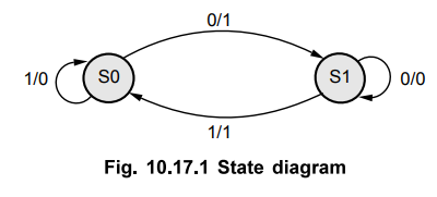
Consider the state diagram shown in Fig. 10.17.1.
•
From the state diagram,
*
If the machine is in state SO and the input signal has a value of 0, then the
machine transitions to state SI and sets the value of the output signal to 1.
*
If the machine is in state SO and the input signal has a value of 1, then the
machine remains in the same state SO and sets the value of the output signal to
0.
•
When the machine is in state SI, its behavior can be described in the same
manner.
•
The VHDL description of state machine having state diagram as shown in Fig. 10.17.1.
As per the state diagram, there are two states. In this code, we are calling
the states SO and SI as state 0 and state 1 respectively. The signal Z
represents the state of the flip-flops. The state_type indicates that Z can
have values state 0 and state 1.
•
The PROCESS statement describes the machine as a sequential circuit.
•
The VHDL description of this state machine is given below.
LIBRARY
IEEE;
USE
IEEE.std_logic_1164.all;
ENTITY
Statemachine IS
PORT(Reset,cIk,
X : IN STD_LOGIC;
Y
: OUT STD_LOGIC);
END
State_machine;
ARCHITECTURE
Behavior OF State_machine IS
TYPE
state_type IS (state0, state1);
SIGNAL
state, next_state : state_type: =state0;
BEGIN
comb_process
: PROCESS (State, X) IS
BEGIN
CASE
State IS - depending upon the current state
WHEN
StateO => - set output signals and next state
IF
X = '0' THEN
next_State
<= State 1;
Y
<= '1';
ELSE
next_State < = StateO;
Y<='0';
END
IF;
WHEN
statel = >
IF
x='l' THEN
next_state<=
state 0;
Y
<='l';
ELSE
next_state <= state 1;
Y<='0';
END
IF;
END
CASE;
END
PROCESS conib_process;
clk_process
: PROCESS IS
BEGIN
WAIT
UNTIL(rising_edge(clk)); - wait until the rising edge
IF
Reset = '1' THEN — check for Reset and initialize state
STATE
<=state_type'left;
ELSE
State < =next_State;
END
IF;
END
PROCESS clk_process;
END
ARCHITECTURE Behavior;
•
We know that state machines are classified as Mealy and Moore. The VHDL
descriptions for both the types of machines are explained in the further
sections.
1. VHDL Code for Mealy-Type State Machines
•
Consider Mealy-type State Machine having state diagram as shown below.
•
The VHDL description of Mealy state machine having state diagram as shown in
Fig. 10.17.2 (a). As per the state diagram, there are two states A and B.

As
given in the VHDL code, the signal Z represents the state of the flip-flops.
The state_type indicates that Z can have the values A and B.
•
The PROCESS statement describes the machine as a sequential circuit. The
signals used by the process are Clock, Resetn, X and Z. Only the Z signal is
modified by the process. The Clock and Resetn are the only signals used by the
process to change Z. So only they are included in the sensitivity list. It is
to be noted that Z is not included in the sensitivity list because any change
in X cannot affect Z until a change occurs in the clock signal.
•
A separate CASE statement is used to define output Y. This CASE statement
describes the logic needed for output Y. It states that when the state machine
is in state A, Y takes the value of X but when it is in state B, Y should be 0.
It is to be noted that the value of Y is not specified inside the CASE
statement which defines the state transitions. The reason is that, in
Mealy-type state machine; the value of output must depend on state of the
machine and on the input signal. Here the CASE statement for the state
transitions is nested inside the IF-THEN statement which waits for a positive
edge clock to occur. So, by placing the code for output Y inside this CASE
statement the output Y could change only as a result of a positive edge clock.
This does not fulfil the requirements of Mealy-type state machine.
•
VHDL code for the Mealy-type state machine.
LIBRARY
IEEE;
USE
IEEE.std_logic_1164.all;
ENTITY
Mealy IS
PORT
(Clock, Resetn, X : IN STD_LOGIC;
Y
: OUT STDLOGIC);
END
Mealy;
ARCHITECTURE
Behavior OF Mealy IS
TYPE
State_type IS (A,B);
SIGNAL
Z : State_type;
BEGIN
PROCESS
(Resetn, Clock)
BEGIN
IF
Resetn = '0' THEN
Z
<=A;
ELSIF(Clock'EVENT
AND Clock = '1') THEN
CASE
Z IS
WHEN
A =>
IF
X='O' THEN Z <=B;
ELSE
Z<=A;
END
IF;
WHEN
B =>
IF
X='O' THEN Z <=A;
ELSE
Z<= B;
END
IF;
END
CASE;
END
IF;
END
PROCESS;
PROCESS(Z,X)
BEGIN
CASE
Z IS
WHEN
A =>
Y<=X;
WHEN
B=>
Y<=0;
END
CASE;
END
PROCESS;
END
Behavior;
a.
VHDL Code for a Serial Adder
•
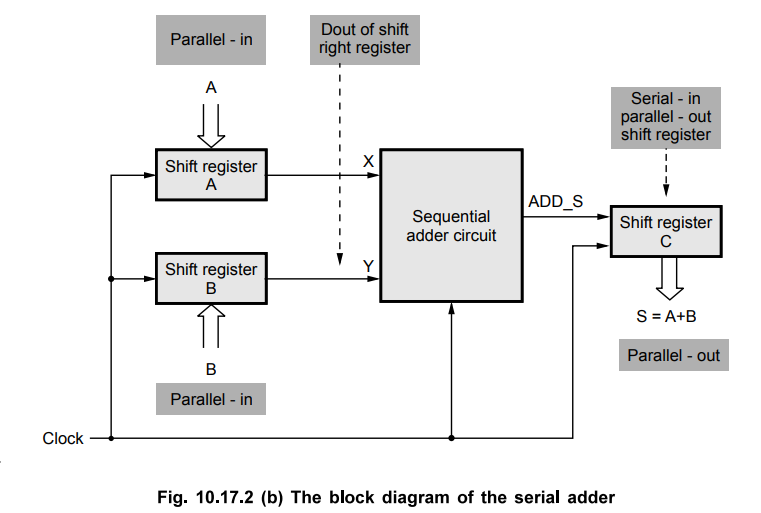
This section explains the VHDL code for a serial adder using Mealy-type FSM.
The code is given at the end of this section. This code is written by taking
the reference of block diagram for the serial adder shown in Fig. 10.17.2 (b),
state diagram for the serial adder FSM shown in Fig. 10.17.2 (c) and state
table for the serial adder FSM shown in Fig. 10.17.2 (d). Go through the
following points for the clear understanding of the VHDL code for a serial
adder.
1.
The number of bits in the serial adder are set by the GENERIC parameter 'length'.
In this code we have taken length equal to 8. Just by changing the length, we
can set the length to any number of bits. The final sum, S is stored in a
buffer having size same as length.
2.
As shown in Fig. 10.17.2 (b), three shift registers are needed for a serial
adder. So we will use the shift register as a subcircuit in the serial adder.
We have discussed the VHDL code for a left-to-right shift register with an
enable input. The code for a serial adder instantiates three shift registers,
one for input A, second for input B and third for the output sum, S.
3.
Active high reset signal is used for the shift registers. When Reset is one,
the circuit is reset and the shift registers are loaded with parallel data.
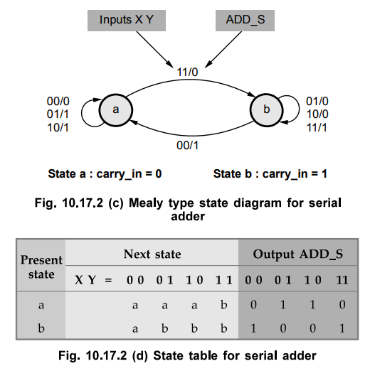
4.
As shown in the state diagram (Fig. 10.17.2 (c)), there are two states a and b.
When the machine is in state a, if both the inputs for FSM adder are high, then
only the machine transitions to state b; otherwise it remains in state a only.
When the machine is in state b, if both the inputs for FSM adder are low, then
only the machine transitions to state a; otherwise it remains in state b only.
5.
According to the state table shown in Fig. 10.17.2 (d) the sum, ADD_S is
calculated by XORing the least significant bits at the outputs of the shift
registers A and B when the machine is in state a and by complementing this
XORed output when the machine is in state b. We are calling the parallel
outputs of shift registers A and B as X and Y respectively. Hence the least
significant bits of these outputs are X(0) and Y(0) respectively.
6.
As discussed in the first point, we are using a left to right shift register
with an enable input as a subcircuit. We are calling this as a COMPONENT
sftregne. Three such components are needed since the serial adder includes
three shift registers. Enable input (EN) of this component is connected to the
signal named high, which is set to 1. There is one more signal in this
component i.e. serial input, I. For the input shift registers A and B, this
signal does not matter. So we can connect it either to 1 or 0. In this code, we
are connecting it to low, which is set to 0. We are using the signals high and
low and then setting them to 1 and 0 respectively because the VHDL syntax does
not allow the constants 0 and 1 to be attached to the ports of a component.
7.
The output shift register C which gives the output sum, S does not need a
parallel data input. It needs only the serial input ADD_S. We are using the
component sftregne for this shift register which has the parallel data input
port. So signal must be connected to it. We are using the signal named 'ZERO'
and setting it to all 0s for this purpose. In the initial part of the code, we
have declared this signal as STD_LOGIC_VECTOR and number of bits in this signal
by the length constant. All the bits of the signal cannot be set to 0 by a
string of 0s inside the double quotes. So we are using the syntax, OTHERS =>
'O'.
8.
After completing the addition of all the input bits and obtaining the output
sum, the adder should be halted. We are using a down counter for this purpose.
When the circuit is reset, this counter is loaded with the number of bits in
the serial adder, i.e. length. During each positive clock edge, the counter is
decremented by one. Thus the counter counts down to 0. When the count reaches
to 0, the counter stops and the further changes in the output shift register C
are disabled.
9.
For shift register COMPONENT sftregne used for shift register, we know that the
'EN' signal is used as an enable input. As long as EN is 1, count loaded in the
down counter (length) is decremented in each clock cycle. When count becomes 0,
EN is set to 0 which stops the operation of the adder. Since we are using a
count which is of type integer, in the condition count = 0, 0 is given without
quotes.
LIBRARY
IEEE;
USE
IEEE.std_logic_1164.all;
ENTITY
Serial IS
GENERIC(length
: INTEGER :=8);
PORT
(Clock : IN STD_LOGIC;
Reset
: IN STDLOGIC;
A.
B : IN STD_LOGIC_VECTOR(length - 1 DOWNTO 0);
S
: BUFFER STD_LOGIC_VECTOR (length - 1 DOWNTO 0));
END
Serial;
ARCHITECTURE
Behavior OF Serial IS
COMPONENT
sftregne
GENERIC(N
: INTEGER := 4);
PORT(R
: IN STD_LOGIC_VECTOR(N-1 DOWNTO 0);
LOAD
EN,I : IN STD_LOGIC;
Clock : IN STD_LOGIC;
Q
: BUFFER STD_LOGIC_VECTOR(N-1 DOWNTO 0));
END
COMPONENT;
SIGNAL
X, Y, Null_in : STD_LOGIC_VECTOR (length-1 DOWNTO 0);
SIGNAL
ADD_S, Low,High, Run : STD_LOGIC;
SIGNAL
Count : INTEGER RANGE 0 TO length;
TYPE
State_type IS : (a,b)
SIGNAL
Z : State_type;
BEGIN
Low
< ='0"; High <=1';
ShiftA
: sftregne GENERIC MAP (n = > length)
PORT
MAP(A, Reset, High, Low, Clock, X);
ShiftB
: sftregne GENERIC MAP (n = > length)
PORT
MAP(B, Reset, High, Low, Clock, Y);
AdderFSM
: PROCESS (Reset, Clock)
BEGIN
IF
Reset = T' THEN
Z
< = a;
ELSIF
Clock'EVENT AND Clock = T' THEN
CASE
Y IS
WHEN
a=>
IF
X(0) = T' AND Y(0) = T' THEN Z<=b;
ELSE
Z<=a;
END
IF;
WHENb=>
IF
X(0)='0' AND Y(0)='0' THEN Z<=a;
ELSE
Z = b;
END
IF;
END
CASE;
END
IF;
END
PROCESS AdderFSM;
WITH
Z SELECT
ADD_S
<= X(0) XOR Y(0) WHEN a
NOT
(X(0) XOR Y(0)) WHEN b;
Null_in
<= (OTHERS => '0');
Shifts
: sftregne GENERIC MAP (n = > length)
PORT
MAP (Null_in, Reset, EN, ADD S, Clock, S);
Stop
: PROCESS
BEGIN
WAIT
UNTIL (Clock'EVENT AND Clock = 1);
IF
Reset = '1' THEN
Count
<= length;
ELSIF
Run = 1' THEN
Count
<= Count-1;
END
IF;
END
PROCESS;
EN
< = 'O' WHEN Count = 0 ELSE '1' ; - stops counter and Shifts
END
Behavior;
2. VHDL Code for Moore-Type State Machines
•
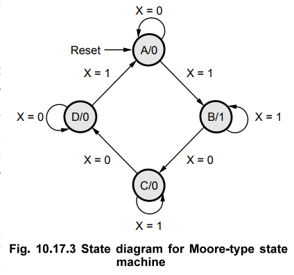
Consider Moore-type state machine having state diagram as shown in Fig.
10.17.3.
•
In this example, we have taken four states A, B, C and D for a state machine.
The state A is selected as a starting state, i.e. the circuit should enter in
state A when power is turned on or when a 'Reset' signal is applied. In
Moore-type state machine, the output value must depend only on the state of the
machine. So the output values are given in each state as shown in state
diagram. For example, A/0 indicates when the machine is in state A, output
value is 0.
•
When the machine is in state A and the input signal X Fjg 1Q „ 3 state djagram
for MowMype state has a value of 0, the machine remains in the same state A machine
and sets the value of the output signal to 0. When the input signal has a value
of 1, then the machine transitions to state B and sets the value of the output
signal to 0.
•
When the machine is in states B, C, D, its behavior can be described in the
same manner.
•
The VHDL description of this state machine is given here.
•
The PROCESS statement describes the machine as a sequential circuit. The
signals used by the process are Clock, Resetn, X and Z. Only the Z signal is
modified by the process. Out of all these signals, only Clock and Resetn
signals are given in the sensitivity list because these are only the signals
used by the process to change Z. It is to be noted that X is not included in
the sensitivity list because any change in X cannot affect Z without a change
in the clock signal.
•
The last part of the VHDL code specifies that if the machine is in state B then
only the output is 1; otherwise output is 0.
LIBRARY
IEEE;
Use
IEEE.std_logic_1164.all;
ENTITY
Moore IS
PORT(Clock,
Resetn, X : IN STD_LOGIC;
Y
: OUT STD_LOGIC);
END
Moore;
ARCHITECTURE
Behavior OF Moore IS
TYPE
state_type IS (A,B,C,D);
SIGNAL
Z : Statetype;
BEGIN
PROCESS
(Resetn, Clock)
BEGIN
IF
Resetn = '0' THEN Z=A;
ELSE
IF(Clock'EVENT AND Clock = '1') THEN
CASE
Z IS
WHEN
A=>
IF
X='0'THEN
Z<=A;
ELSE
Z<=B;
END
IF;
WHEN
B = >
IF
X = '0' THEN
Z<=C;
ELSE
Z<=B;
END
IF;
WHEN
C=>
IF
X='0'THEN
Z<=D;
ELSE
Z<=C;
END
IF;
WHEND=>
IF
X='0'THEN
Z<=D;
ELSE
Z<=A;
END
IF;
END
CASE;
END
IF;
END
PROCESS;
Y<='1'WHEN
Z=B ELSE 'O';
END
Behavior
Review Questions
1. Write a VHDL code
for any Mealy-type state machine.
2. Write a VHDL code
for any Moore-type state machine.
3. Write a VHDL code
for a 4-bit universal shift register.
AU: Dec.-14, Marks 8
Digital Logic Circuits: Unit V: VHDL : Tag: : - VHDL Description for Finite State Machines (FSM)
Related Topics
Related Subjects

Digital Logic Circuits
EE3302 3rd Semester EEE Dept | 2021 Regulation | 3rd Semester EEE Dept 2021 Regulation