Electric Circuit Analysis: Unit II: Network Reduction and Theorems for dc and ac Circuits
Voltage and Current source transformation
For the mesh method of analysis, it is easier if the circuit has voltage sources. In the nodal analysis, it is easier if the circuit consists of current sources.
SOURCE TRANSFORMATION
(VOLTAGE AND CURRENT SOURCE TRANSFORMATION)
For
the mesh method of analysis, it is easier if the circuit has voltage sources.
In the nodal analysis, it is easier if the circuit consists of current sources.
In several cases, we may have to convert one type of source into another. This
is for both A.C and D.C. circuits.
Figure.2.4
(a) shows an ideal voltage source in series with a resistance. Across the
terminals A and B of the device, the voltage is e.
e
= E- iR ... (1)
Figure.2.4
(b) shows a current source in parallel with a resistance. In this case, the
current through R = I - i.
Voltage
across R = e = (I - i) × R
=
IR – iR ... (2)
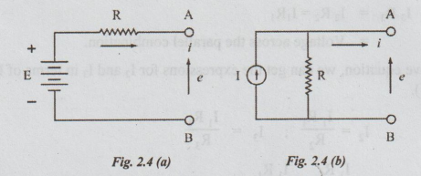
The
equations (1) and (2) shown above are identical if E = IR.
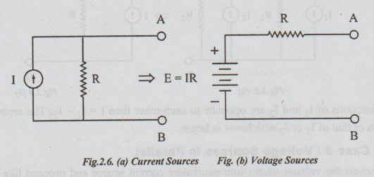
Thus
a current source in parallel with a resistance is equivalent to a voltage
source in series with the same resistor, provided that the value of the voltage
source is equal to the value of the current source, multiplied by the
resistance. The conversion is valid in either direction and is shown in the
figures 2.4 (a) and (b). The polarities of the sources are to be clearly noted
in these examples.

In
the above figures, for example, if E = 9 volts and R = 2 ohms, then I = 9 / 24.5
amperes and R remains same.
In
the above current source, if I = 10 amperes and R = 3 ohms, then in the equivalent
voltage source E = IR = 10 × 3 = 30 volts and R remains same i.e.,3 ohms.
1. (a) Combination of Energy Sources
The
following rules are followed to replace combination of sources by single
equivalent source.
Case
1: Series Combination of Voltage Sources
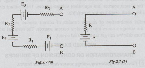
Refer
figure 2.7(a), where 3 voltage sources are in series between the terminals A
and B. Its equivalent single source is shown in figure 2.7 (b) where E = E1
+ E2 – E3 and R = R1 + R2 + R3.
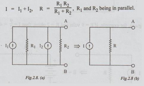
(b) Case 2: Current Sources in Parallel
In
figure 2.8 (a), current sources are shown in parallel. This can be replaced by
a single current source, as shown in figure 2.8 (b).
If
the directions of I1 and I2 are opposite to each other
then I = I1 ~ I2. The arrow for I will be in the
direction of that of I1 or 12 whichever is larger.
(c) Case 3: Voltage Sources in Parallel
First,
convert the voltage source into equivalent current source and proceed like case
2 to get the equivalent current source. If necessary, the current source can be
replaced by equivalent voltage source by using the formula.
(d) Case 4: Current Sources in Series
Here,
convert the current sources into equivalent voltage sources and simplify the
combination as this comes under case 1.
Note:
1.
Simplification of series connection of the sources is possible, if they are
voltage sources.
2.
Simplification of parallel connection of source is possible, if they are
current sources.
3.
If a series combination of sources consists of current sources and voltage sources,
then first convert the current sources into equivalent voltage sources. The
resultant circuit comes under case 1, after which simplification is possible.
ww
4.
If a parallel combination of sources consists of current sources and voltage
sources, then convert the voltage sources into equivalent current sources. The
resultant circuit comes under case 2. From this, we can get the simplified
circuit.
Electric Circuit Analysis: Unit II: Network Reduction and Theorems for dc and ac Circuits : Tag: : - Voltage and Current source transformation
Related Topics
Related Subjects

Electric Circuit Analysis
EE3251 2nd Semester 2021 Regulation | 2nd Semester EEE Dept 2021 Regulation