Digital Logic Circuits: Unit III: (a) Flip-Flops
Flip-Flop
Circuit diagram, Logic symbol, Truth table, Characteristic equation
• T flip-flop is also known as 'Toggle flip-flop'. The T flip-flop is a modification of the JK flip-flop.
Flip-Flop
AU
: May-17, Dec.-17, 18
•
T flip-flop is also known as 'Toggle flip-flop'. The T flip-flop is a
modification of the JK flip-flop. As shown in the Fig. 4.6.1, the T flip-flop
is obtained from a JK flip-flop by connecting both inputs, J and K together.
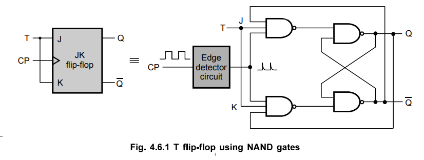
•
When T = 0, J = K = 0 and hence there is no change in the output. When T = 1, J
= K = 1 and hence output toggles.
•
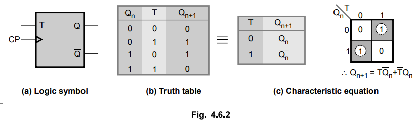
The Fig. 4.6.2 shows logic symbol, truth table and the characteristic equation
for T flip-flop.
Review Question
1. Explain the T flip-flop.
2. Describe the design procedure with neat diagram about 4 bit
bidirectional shift register with parallel load.
Digital Logic Circuits: Unit III: (a) Flip-Flops : Tag: : Circuit diagram, Logic symbol, Truth table, Characteristic equation - Flip-Flop
Related Topics
Related Subjects

Digital Logic Circuits
EE3302 3rd Semester EEE Dept | 2021 Regulation | 3rd Semester EEE Dept 2021 Regulation