Physics for Electrical Engineering: Unit I: Dielectric Materials and Insulation
Capacitor materials typical capacitor construction
The selection of right dielectric materials for capacitor applications is based on various parameters like value of capacitance, frequency, tolerance size and operating voltage.
CAPACITOR
MATERIALS TYPICAL CAPACITOR CONSTRUCTION
Dielectric
materials are used to manufacture capacitors of different ranges. The selection
of right dielectric materials for capacitor applications is based on various
parameters like value of capacitance, frequency, tolerance size and operating
voltage.
Dielectric
materials such as paper and plastic film, mica film, single layer ceramic,
multilayer ceramic, solid electrolytic (Al, Ta) and electrolytic (Al, Ta) are
used in capacitors to obtain a range of capacitance 1 pf to 104 mf.
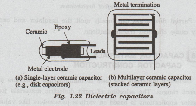
1. Single and multilayer dielectric capacitors
The
diagramatic representation of a single layer capacitor is shown in fig. 1.22.
It consists of a thin ceramic disk or plate placed in-between the metal
electrodes. The leads for the electrical connections are taken from the metal
electrode.
In
order to prevent the degradation of dielectric ceramic plate it is encapsulated
in an epoxy coating.
The
capacitance of single layer capacitor for an area of 1 cm2 is 885
pf. The capacitance of the capacitor by connecting N number of ceramic plate in
parallel by providing a sufficient space as shown in fig. 1.22(b).
The
capacitor with stacking of ceramic plates in different layers is known as
multilayer capacitor. The capacitance of multilayer capacitor is in the range
of a few hundred microfarads.
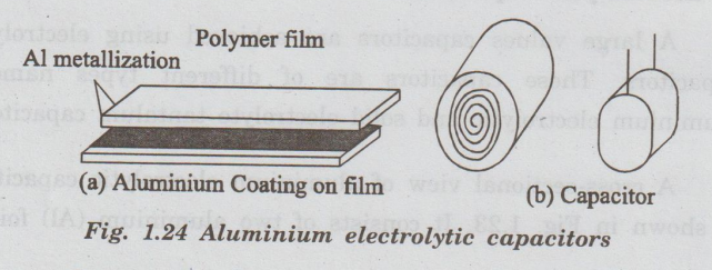
2. Polymeric film capacitors
Polymer
thin film capacitors are as mid-frequency capacitors. The two metal coated
polymer films are placed in parallel. In order to get the capacitor, the two
metal sheets are rolled together like Swiss roll.
The
electrical connections are taken from the opposite sides of the metals by
proper soldering. A multilayer polymeric thin film capacitors like multilayer
ceramic capacitors can also be produced.
3. Electrolytic capacitors
A
large values capacitors are achieved using electrolytic capacitors. These
capacitors are of different types namely, aluminium electrolytic and solid
electrolyte tantalum capacitors.
A
cross-sectional view of aluminium electrolytic capacitors is shown in Fig.
1.23. It consists of two aluminium (Al) foils.
A
thin layer of Al2O3 as a dielectric medium is grown on
the rough surface of one of the foils. The two foils are wound together in the
form of cylinder. They kept inside the cylindrical case as shown in fig. 1.23.
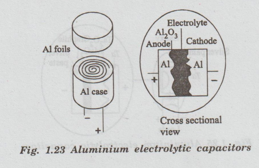
The
thickness of Al2O3, grown on the foil is 0.1 μm and hence, it gives
large capacitance value (i.e., small thickness and large area.
The Al2O3 is grown on
the Al foil electrolytically and hence, the capacitor is known as electrolytic
capacitor.
A
thin film of Al2O3 dielectric coated on the surface of Al
foil act as anode. Al foil acts as a cathode.
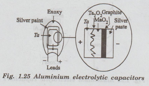
The
structure of a solid electrolyte tantalum capacitor is shown in fig. 1.24(a).
The anode is made up of tantalum (Ta) pellet. The surface of Ta pellet is
anodized to get the tantalum pentoxide (Ta2O3).
A
thick solid electrolyte like MnO2 is coated above Ta2O2.
The process is completed by coating graphite and silver paste as shown in fig.
1.25. The above system is then coated by an epoxy. Tantalum capacitors are
widely used in electronic applications.
Physics for Electrical Engineering: Unit I: Dielectric Materials and Insulation : Tag: : - Capacitor materials typical capacitor construction
Related Topics
Related Subjects

Physics for Electrical Engineering
PH3202 2nd Semester 2021 Regulation | 2nd Semester EEE Dept 2021 Regulation