Electric Circuit Analysis: Unit I: a. Introduction
Phasor Algebra
Examples Solved Problems
In the rectangular form, if the active part is zero, the impedance is purely reactive. +j indicates inductive reactance - j indicates capacitive reactance.
PHASOR
ALGEBRA
To represent R, XL, XC
in rectangular form:
ZR
= R + j0
ZL
= 0 + j XL
ZC
= 0 - jXC
To represent R, XL, XC
in polar form :
ZR
=R ∠ 0°
ZL
= XL ∠ 90°
ZC
= XC ∠ -90°
Note:
1.
In the rectangular form, if the reactive part (coefficient of j) is zero, the
impedance is purely resistive.
2.
In the rectangular form, if the active part is zero, the impedance is purely
reactive. +j indicates inductive reactance -j indicates capacitive reactance.
3.
In the polar form, if the angle is zero, the impedance is purely resistive.
4.
In the polar form, if the angle is 90°, the impedance is purely reactive. +90°
indicates inductive reactance and -90° indicates capacitive reactance.
For
addition and subtraction, complex notation (rectangular) form is useful. For
multiplication and division, polar form is necessary. So, the students should
know conversion of rectangular to polar form and vice versa. For more details,
the student can refer to the instructions of the Scientific Calculator.
Converting rectangular to polar
form:
Example 1: Let Z = (10+ j15).
Convert this into polar form. [Note: The author had used
the scientific calculator CASIO fx 82B)
Solution:
Steps:
1.
Display 10
2.
Press Shift key
3.
Press R→P
4.
Display 15.
5.
Press = It shows 18.03 Ω
6.
Press x →y It show the angle 56.31°
7.
In the polar form, now Z is written as Z = 18.03 ∠56.31°
Example
2: Convert 20-j15 into polar form.
Solution: Steps:
1. Display 20
2. Press Shift key
3. Press R→P
4. Display -15.
5. Press = It shows 25 Ω
6. Press x → y It shows the angle -36.9°
7. In the polar form, now Z is written as Z = 25 ∠-36.9°
Note:
1. The student should not forget to put '-' in the
reactive part.
2. The angle of Z always shows the phase angle ϕ.
cos ϕ is called the power factor.
Converting
polar to rectangular form
Example
3: Convert Z = 10 ∠60°
into rectangular form.
Solution: Steps:
1. Display 10
2. Press Shift key
3. Press P →R
4. Display 60
5. Press = It show 5 (active part)
6. Press x → y It shows 8.66 (reactive part)
7. So, Z = 5 + j 8.66.
Example
4: Convert Z = 30 ∠45°
into rectangular form.
Solution: Steps:
1. Display 30
2. Press Shift key
3. Press P→R
4. Display 45°
5. Press -/+
6. Press = It displays 21.21 (active part)
7. Press x→y It shows-21.22 (reactive part)
8. So, Z = 21.21-j21.21
Note:
1.
The calculator must be set in 'deg' mode for conversions
2.
In the polar form, if the angle is 90°, in the rectangular form active (real)
part is 0.
3.
In the polar form, if the angle is 45°, in the rectangular form, active and
reactive parts are equal to each other.
4.
Put j before reactive part.
Example 5 Z1=10+j10 and
Z2 = 20-30 are in series. Find the ZT in polar form.
Solution:
ZT
= Z1+Z2 = 10 + j10 + 20 - j30 = 30 - j20
ZT
= 36.1 ∠-33.7°
Note:
The phase angle here is 33.7°. Since it is negative, the impedance is
capacitive. So ϕ is leading in nature.
Example 6:
The total impedance of a circuit in
which Z1 and Z2 are in series is equal to (30+j40)
Ω.
Z1 = (20+j60) Ω. Find Z2.
Solution:
Steps:
ZT
= Z1 + Z2
Z2
= ZT - Z1
=
(30+j40) - (20+j60)
=
10-j20 {rectangular form}
=
22.36 ∠-63.43° {Polar form}
Example 7: In a given circuit I =
10∠60°
Z = 20∠30. Find V.
Solution:
V
= I. Z = (10 ∠ 60°)
(20 ∠30°)
=(10
× 20) ∠ (60+30) = 200 ∠90°.
Example 8: In a circuit V = 200
volts I = 10∠30°. Find Z both in polar and
rectangular forms.
Solution:
I
= V/Z . It is division. So both V and I must be in polar form. Since angle of V
is not given, we can take it as 0°, So,
V
= 200 ∠ 0° and
I
= 10 ∠ 30°
Z
= V/I
=
200∠ 0°/10 ∠ 30°
=
200/10 ∠ (0-30)
=20∠-30° { Polar form}
=17.32-j10
{ rectangular form}
Table 1:
Circuit response of single elements
for DC:
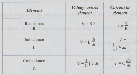
Table 2:
Voltage across each element for i = Im sin ωt → I = |I| ∠20°
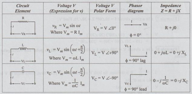
Where
ϕ is the phase angle
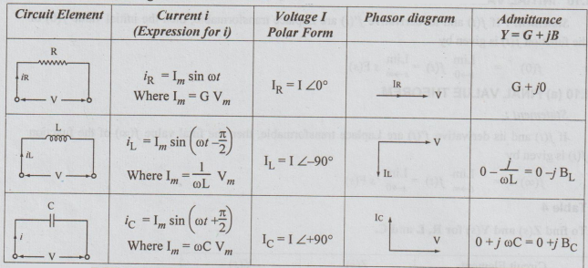
Table 3:
Current through each element when v = Vm sin ωt → V = V∠0°
Electric Circuit Analysis: Unit I: a. Introduction : Tag: : Examples Solved Problems - Phasor Algebra
Related Topics
Related Subjects

Electric Circuit Analysis
EE3251 2nd Semester 2021 Regulation | 2nd Semester EEE Dept 2021 Regulation