Electric Circuit Analysis: Unit I: a. Introduction
Short circuit (sc)
Explanation with circuit Diagram, Illustration
Short circuit between any two points can be defined in terms of a figure. If a circuit element is replaced by a short length of an ideal conductor, the terminals are said to be short circuited
SHORT CIRCUIT
(SC)
Short
circuit between any two points can be defined in terms of a figure. If a
circuit element is replaced by a short length of an ideal conductor, the
terminals are said to be short circuited
The
voltage across the short circuit is always zero regardless of the current
through it. The current in the short circuit depends upon the circuit connected
to the terminals. Thus, a short circuit is a two- terminal element for which
voltage must be zero when the current is not zero.
Mathematically,
V(t) = 0, i(t) ≠ 0.
A
short length of copper or aluminium wire can be used for short circuiting.

The
concept of short circuit can be clearly understood from the following
illustrations.
Illustration
1:
Consider
the circuit given below. Here, the terminals C and D are short circuited.

i.e.,
R2 is short circuited. Between C and D, the resistance is 0. The
effective resistance to the source, V1= R1 + 0 = R1
Current from the source
I1
= V1 / R1
All
this current will flow through the short circuited path.
Note
1: If there is one more short circuit between C and D,
the current through each short circuited path is equal to I1 / 2
2:
If there are n short circuit paths between C and D, the current through each
path is equal to I1 / n.
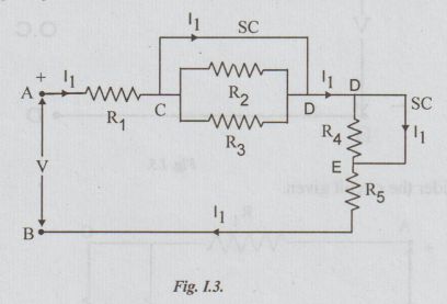
Illustration 2:
Consider
circuit in the figure. Between terminals C and D, there are 3 parallel paths.
One of them is a short circuit. So all the current flowing through R1
flows through this short circuit.
It
will not flow through R2 or R3. Again, between D and E
terminals, there is a short circuit. The current through this path is I1
as shown in the figure. Current through R5 is I1.
The
total resistance to the source is
=
RAC+ RCD+ RDE + REB = R1+0+0+
R5
=
R1 + R5
So,
I1 = V / R1+R5 {ohm's law}
Note:
1.
The resistance R2, R3 R4 are not effective,
whatever may be their values. It is because they are short circuited.
2.
The current through resistances which are short circuited will always be zero.
Electric Circuit Analysis: Unit I: a. Introduction : Tag: : Explanation with circuit Diagram, Illustration - Short circuit (sc)
Related Topics
Related Subjects

Electric Circuit Analysis
EE3251 2nd Semester 2021 Regulation | 2nd Semester EEE Dept 2021 Regulation